Speaker box and electronic equipment with same

A speaker box and speaker technology, which is applied in the direction of sensors, loudspeakers, electrical components, etc., can solve the problems of speaker box high-order harmonic increase, speaker box mid-frequency distortion, and sound crosstalk of sound holes, etc., to reduce high-order Harmonic components, ensure the output sound quality, and reduce the effect of sound crosstalk

Inactive Publication Date: 2016-11-23
AAC TECH PTE LTD
View PDF6 Cites 15 Cited by
  • Summary
  • Abstract
  • Description
  • Claims
  • Application Information

AI Technical Summary

Problems solved by technology

[0006] The purpose of the present invention is to provide a speaker box, which is used to solve the technical problems of high mid-frequency distortion of the existing speaker box, decrease in sense of hearing caused by increase of high-order harmonics of the speaker box of the related art, and crosstalk to the sound of the sound hole

Method used


Image

  • Speaker box and electronic equipment with same
  • Speaker box and electronic equipment with same
  • Speaker box and electronic equipment with same

Examples


Embodiment 1

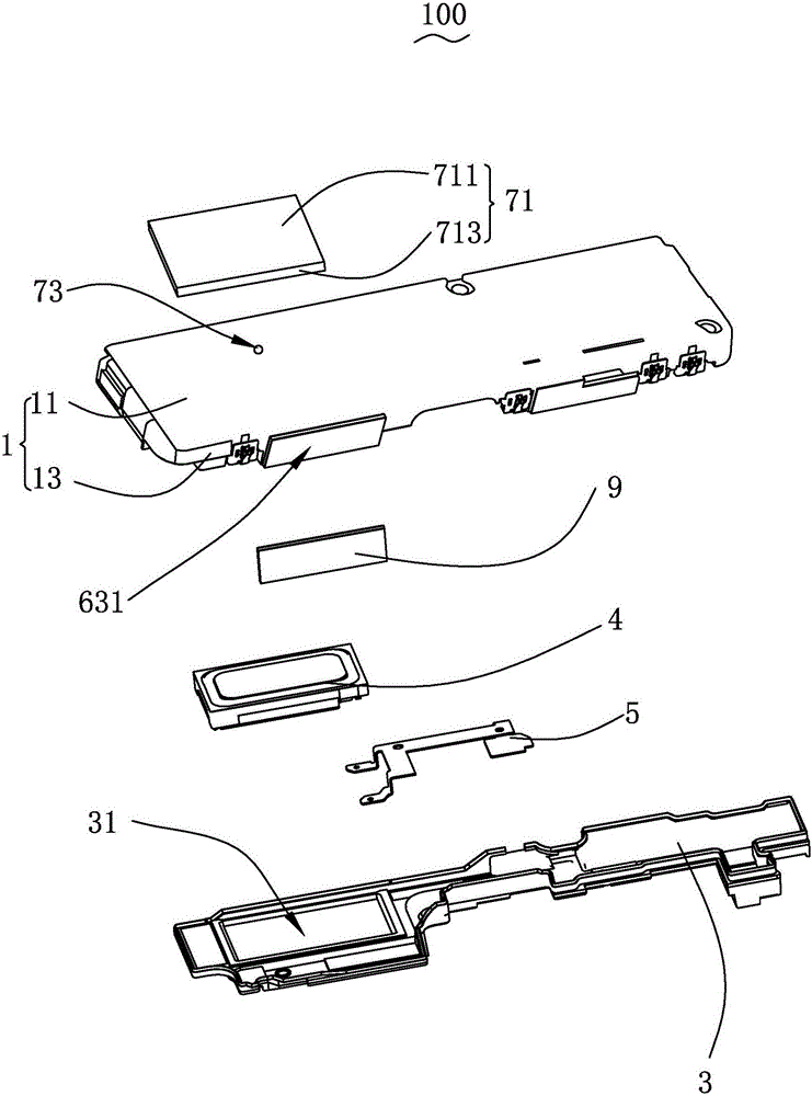
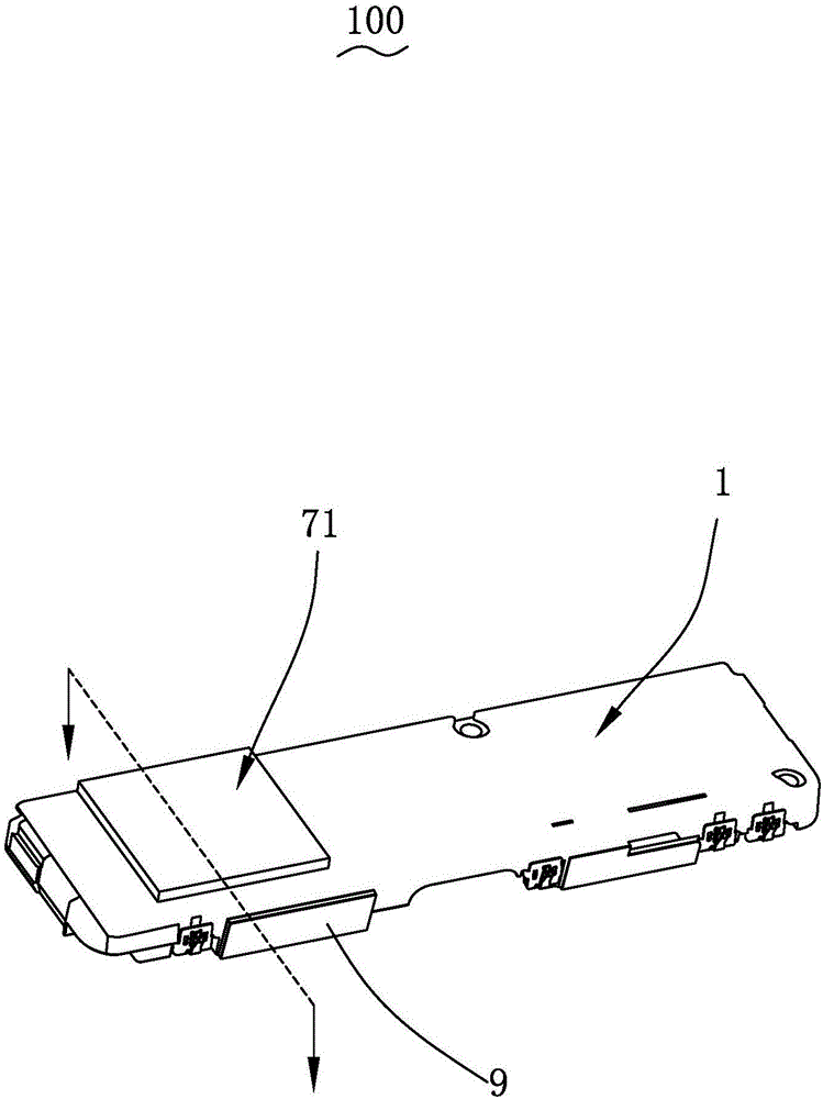
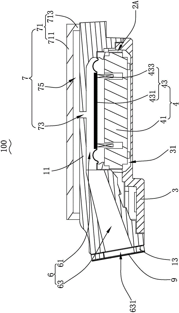
[0028] Please also see figure 1 , figure 2 and image 3 ,in, figure 1 A perspective exploded schematic diagram of a preferred embodiment of the speaker cabinet provided by the present invention; figure 2 for figure 1 The three-dimensional assembly diagram of the speaker box shown; image 3 for figure 2 A sectional view of the speaker cabinet shown along line A-A. The present invention provides a speaker box 100, which includes an upper cover 1, a lower cover 3 that is combined with the upper cover 1 to form a storage space 2A, a speaker unit 4 accommodated in the storage space 2A, and the speaker The flexible circuit board 5 electrically connected to the monomer 4, the front chamber 6 and the leakage structure 7 communicated with the external environment.

[0029] The upper cover 1 includes a top wall 11 and an upper cover side wall 13 extending from the top wall 11 to a direction away from the top wall 11 , the number of the upper cover side walls 13 is four and con...

Embodiment 2

[0040] Please refer to Figure 4 and Figure 5 , Figure 4 It is a three-dimensional assembly diagram of Embodiment 2 of the speaker cabinet provided by the present invention, Figure 5 for Figure 4 A sectional view of the speaker cabinet shown along line A-A.

[0041] The structure of the second embodiment is basically the same as that of the first embodiment. The difference between the speaker box 200 and the speaker box 100 is that the leakage structure 7 also includes a sound-absorbing material 77 covering the leakage hole 73, which can be used to absorb The high-order harmonics of the leakage hole 73 reduce the crosstalk of the sound from the sound outlet 631 . The sound-absorbing material 77 may cover the end of the leakage hole 73 communicating with the cavity 75 and be located on the surface of the top wall 11 facing the bottom plate 711, or the sound-absorbing material 77 may cover the leakage hole 73 communicates with the front cavity 6 and is located on the su...


PUM


Abstract

The invention provides a speaker box which comprises an upper cover, a lower cover forming an accommodating space with the upper cover and a speaker body accommodated in the accommodating space. The speaker body comprises a vibrating diaphragm, the upper cover and the vibrating diaphragm enclose to form a front sound cavity, a sound channel used for guiding sound generated from the speaker body is further arranged in the speaker box, and the front sound cavity and the sound channel commonly form a front cavity; the speaker box further comprises a leakage structure, the leakage structure comprises a sealing cover arranged above the upper cover and a leakage hole penetrating the upper cover, the upper cover and the sealing cover enclose to form a cavity, and the leakage hole is communicated with the front cavity and the cavity. The invention further provides electronic equipment with the speaker box. Compared with the prior art, the speaker box is low in intermediate frequency distortion, weak in high-frequency resonant, low in radio-frequency component, good in sound feeling and free of sound crosstalk from sound holes.

Description

【Technical field】 [0001] The invention relates to the field of electroacoustic conversion, in particular to a speaker box and electronic equipment with the speaker box. 【Background technique】 [0002] With the advent of the mobile Internet era, the popularity of audio equipment is getting higher and higher. People's requirements for audio equipment are not limited to video and audio playback, but also put forward more requirements for the reliability of audio equipment. Especially with the advent of the 4G era, mobile multimedia technology has also developed. Many audio devices have multiple entertainment functions, such as video playback, digital photography, games, GPS navigation, etc. [0003] In audio equipment, a speaker box is a commonly used electronic component, mainly used for playing audio signals. A speaker box in the prior art includes an upper cover, a lower cover that is assembled with the upper cover to form a storage space, and a speaker unit that is accommo...

Claims


Application Information

Patent Timeline
Patent Type & Authority Applications(China)
IPC IPC(8): H04R9/06H04R9/02
CPCH04R9/02H04R9/06H04R2400/11
Inventor 秦鹏魏威蔡斌
Owner AAC TECH PTE LTD
Why Eureka
Try Eureka