Ignition device

An ignition device and ignition coil technology, which is applied to other devices, engine ignition, ignition controllers, etc., can solve the problems of increasing the discharge current of the spark plug, reducing the discharge current, and unable to maintain the spark discharge, so as to ensure and improve the ignitability Effect

Active Publication Date: 2016-11-23
DENSO CORP
View PDF5 Cites 3 Cited by
  • Summary
  • Abstract
  • Description
  • Claims
  • Application Information

AI Technical Summary

Problems solved by technology

[0003] However, according to the technique of Patent Document 1, if the on-periods of the first and second switch parts overlap, the discharge current decreases rapidly and spark discharge cannot be maintained. Conversely, if the off-periods of the first and second switch parts overlap, Then the discharge timing overlaps, the discharge current increases sharply and causes greater damage to the electrode in the spark plu

Method used


Image

  • Ignition device
  • Ignition device
  • Ignition device

Examples


Embodiment 1

[0034] [Structure of Embodiment 1]

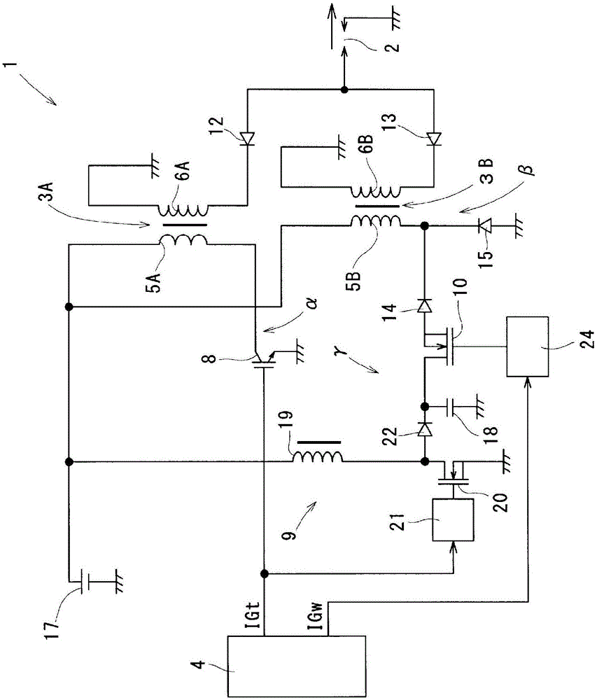
[0035] refer to figure 1 The ignition device 1 of the first embodiment will be described.

[0036] The ignition device 1 is mounted on a spark ignition engine for running a vehicle, and ignites an air-fuel mixture in a combustion chamber at a predetermined ignition timing. In addition, an example of an engine is a direct-injection engine capable of performing lean burn (lean burn) using gasoline as fuel, and is equipped with a swirl flow control mechanism that generates a swirl flow of the mixture gas such as tumble flow or swirl flow in the cylinder. . In addition, in an operating state in which the gas flow rate in the cylinder is high and blowout of spark discharge may occur, such as lean burn, the ignition device 1 is controlled so as to perform continuous spark discharge in addition to main ignition.

[0037] In addition, the ignition device 1 is a DI (direct ignition) type, and supplies electric energy to one spark plug 2 of each c...

Embodiment 2

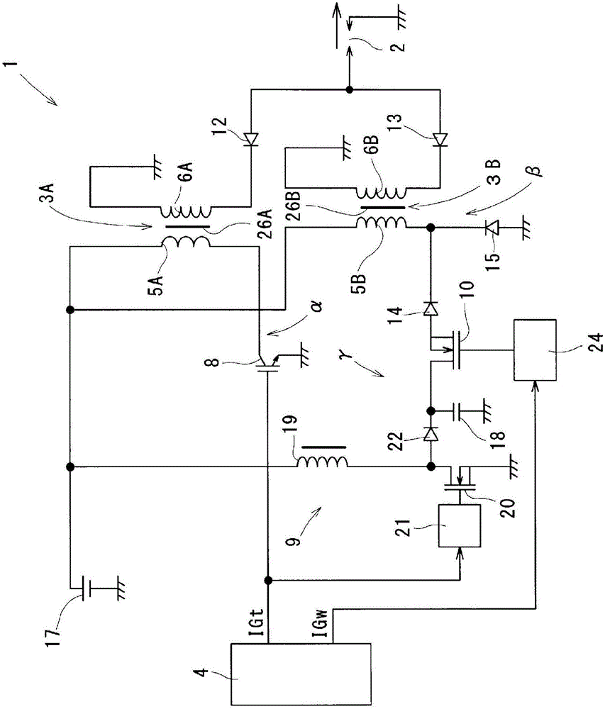
[0078] refer to image 3 , Figure 4 (a) and Figure 4 (b) Example 2 will be described focusing on points different from Example 1. FIG. In addition, in Example 2, the same code|symbol as said Example 1 shows the same functional thing.

[0079] The ignition device 1 of the second embodiment includes first and second magnets 26A and 26B of reverse bias magnetic polarity described below. First, the first magnet 26A is provided in the iron core 27A through which the magnetic flux generated by the energization to the primary coil 5A passes, and reversely biases the iron core 27A. Moreover, the 2nd magnet 26B is provided separately from the 1st magnet 26A, and is provided in the iron core 27B which passes the magnetic flux which generate|occur|produces by energizing the primary coil 5B, and reverse-biases the iron core 27B.

[0080] That is, when the main ignition occurs, the iron core 27A is reversely biased by the first magnet 26A, and the variation range of the magnetic flux...

Embodiment 3

[0087] refer to Image 6 , Example 3 will be described centering on points different from Example 1. In addition, in Example 3, the same code|symbol as said Example 1 shows the same functional thing.

[0088] According to the ignition device 1 of embodiment 3, such as Image 6 As shown, the first end of the primary coil 5B is connected to the ground potential.

[0089] As a result, with regard to the freewheeling path of the electromotive force accompanying the switching of the second switch unit 10 , it is possible to reduce the target potential from the primary coil 5B to that of the first embodiment. Therefore, the step-up range of the booster circuit 9 can be reduced, so various components used in the booster circuit 9 (capacitor 18, boost switch unit 20, diode 22, etc.) For the second switch unit 10, an element with a low withstand voltage is used. As a result, cost reduction and volume reduction of the ignition device 1 and improvement in storage efficiency of electr...


PUM


Abstract

In this ignition device (1), a first switching unit (8) imparts a voltage between the electrodes of a spark plug (2) by means of turning on/off the electrification from a vehicle-mounted battery (17) to a primary coil (5A). Also, a second switching unit (10) imparts, in the same direction as that generated by means of the turning on/off of the first switching unit (8), a voltage between the electrodes of the spark plug (2) by introducing electrical energy stored at a voltage boosting circuit (9) to a primary coil (5B). As a result, it is possible for the complexity of turning on/off the first and second switching units (8, 10) to be reduced to a greater degree than has been conventional.

Description

technical field [0001] The present invention relates to ignition devices for use in internal combustion engines. Background technique [0002] As an ignition device, there is known an ignition device for an internal combustion engine that applies electric energy to one spark plug from two ignition coils (for example, refer to Patent Document 1). According to this technique, a first switch unit for turning on and off the primary coil of one ignition coil from the on-vehicle battery and a second switch unit for turning on and off the primary coil of the other ignition coil from the on-vehicle battery are provided. switch department. In addition, the first and second switch units alternately repeat the on-off operation by the so-called all-transistor method so that the on-periods of the first and second switch units do not overlap. Thereby, a stable discharge state without discharge interruption can be maintained. [0003] However, according to the technique of Patent Docume...

Claims


Application Information

Patent Timeline
IPC IPC(8): F02P3/00F02P3/08F02P9/00
CPCF02P3/0442F02P3/0892F02P5/15F02P9/007F02P15/10F02P3/08F02P9/00
Inventor 鸟山信竹田俊一寺田金千代中山觉大野贵士
Owner DENSO CORP
Why Eureka
Try Eureka