ignition device
An ignition device and ignition coil technology, which is applied to other devices, engine ignition, ignition controllers, etc., can solve the problems of increasing discharge current to spark plugs, reducing discharge current, electrode damage, etc., and achieves the effect of ensuring ignition and improving ignition
- Summary
- Abstract
- Description
- Claims
- Application Information
AI Technical Summary
Problems solved by technology
Method used
Image
Examples
Embodiment 1
[0034] [Structure of Embodiment 1]
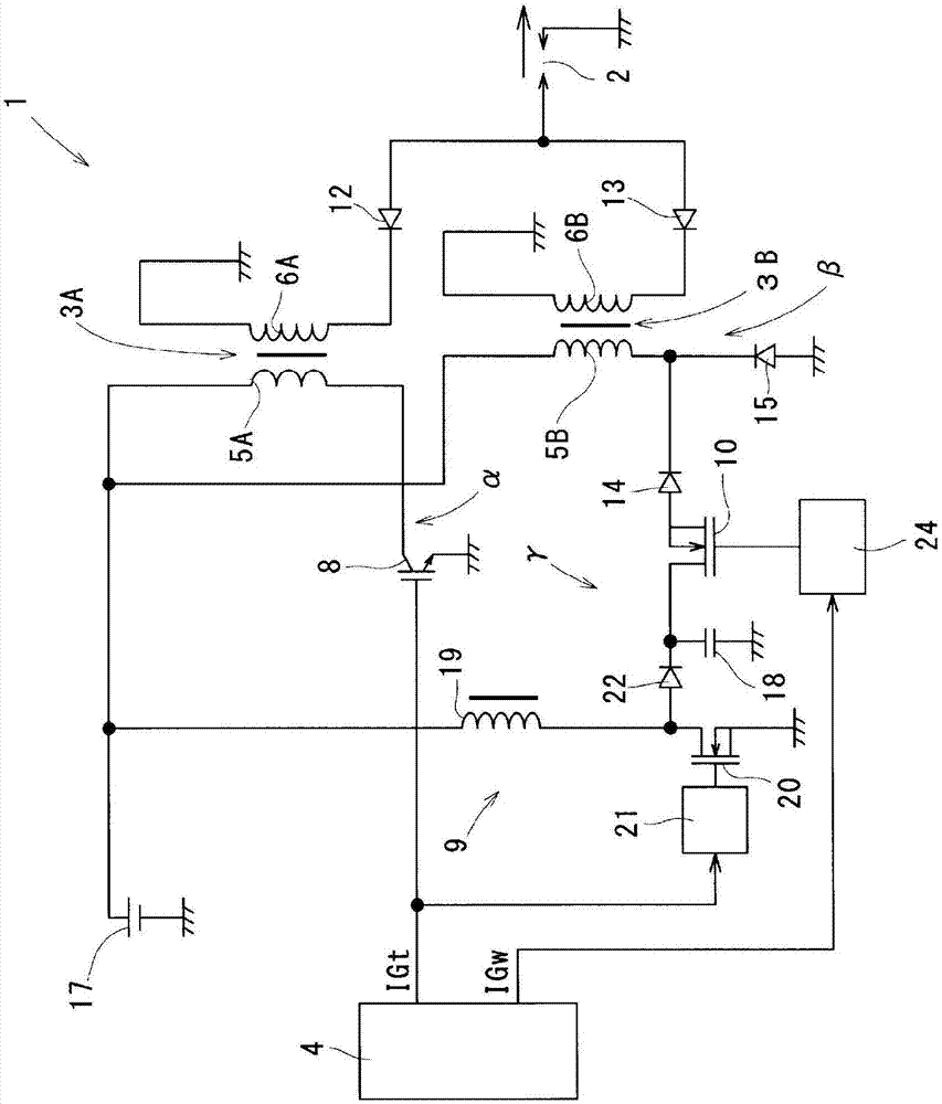
[0035] refer to figure 1 The ignition device 1 of the first embodiment will be described.
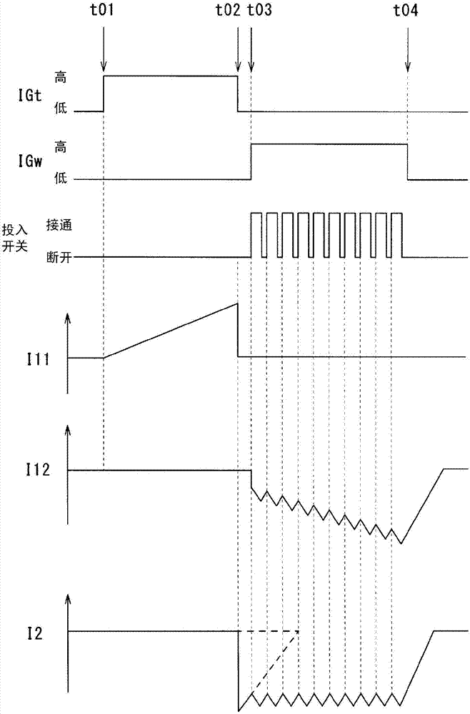
[0036] The ignition device 1 is mounted on a spark ignition engine for running a vehicle, and ignites an air-fuel mixture in a combustion chamber at a predetermined ignition timing. In addition, an example of an engine is a direct-injection engine capable of performing lean burn (lean burn) using gasoline as fuel, and is equipped with a swirl flow control mechanism that generates a swirl flow of the mixture gas such as tumble flow or swirl flow in the cylinder. . In addition, in an operating state in which the gas flow rate in the cylinder is high and blowout of spark discharge may occur, such as lean burn, the ignition device 1 is controlled so as to perform continuous spark discharge in addition to main ignition.
[0037] In addition, the ignition device 1 is a DI (direct ignition) type, and supplies electric energy to one spark plug 2 of each c...
Embodiment 2
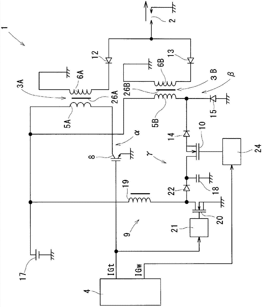
[0078] refer to image 3 , Figure 4 (a) and Figure 4 (b) Example 2 will be described focusing on points different from Example 1. FIG. In addition, in Example 2, the same code|symbol as said Example 1 shows the same functional thing.
[0079] The ignition device 1 of the second embodiment includes first and second magnets 26A and 26B of reverse bias magnetic polarity described below. First, the first magnet 26A is provided in the iron core 27A through which the magnetic flux generated by the energization to the primary coil 5A passes, and reversely biases the iron core 27A. Moreover, the 2nd magnet 26B is provided separately from the 1st magnet 26A, and is provided in the iron core 27B which passes the magnetic flux which generate|occur|produces by energizing the primary coil 5B, and reverse-biases the iron core 27B.
[0080] That is, when the main ignition occurs, the iron core 27A is reversely biased by the first magnet 26A, and the variation range of the magnetic flux...
Embodiment 3
[0087] refer to Image 6 , Example 3 will be described centering on points different from Example 1. In addition, in Example 3, the same code|symbol as said Example 1 shows the same functional thing.
[0088] According to the ignition device 1 of embodiment 3, such as Image 6 As shown, the first end of the primary coil 5B is connected to the ground potential.
[0089] As a result, with regard to the freewheeling path of the electromotive force accompanying the switching of the second switch unit 10 , it is possible to reduce the target potential from the primary coil 5B to that of the first embodiment. Therefore, the step-up range of the booster circuit 9 can be reduced, so various components used in the booster circuit 9 (capacitor 18, boost switch unit 20, diode 22, etc.) For the second switch unit 10, an element with a low withstand voltage is used. As a result, cost reduction and volume reduction of the ignition device 1 and improvement in storage efficiency of electr...
PUM
 Abstract
Description
Claims
Application Information
 - R&D
- Intellectual Property
- Life Sciences
- Materials
- Tech Scout
- Unparalleled Data Quality
- Higher Quality Content
- 60% Fewer Hallucinations
Browse by: Latest US Patents, China's latest patents, Technical Efficacy Thesaurus, Application Domain, Technology Topic, Popular Technical Reports.
© 2025 PatSnap. All rights reserved.Legal|Privacy policy|Modern Slavery Act Transparency Statement|Sitemap|About US| Contact US: help@patsnap.com


