Variable speed drive and method for machining a variable speed drive

A technology of variable speed drive and action, which is applied to transmission parts, electromechanical devices, electric components, etc., and can solve problems such as reducing service life

Inactive Publication Date: 2021-03-12
ROBERT BOSCH GMBH
View PDF1 Cites 0 Cited by
  • Summary
  • Abstract
  • Description
  • Claims
  • Application Information

AI Technical Summary

Problems solved by technology

However, during this running-in process, which takes place under increased load, the meshing points between the armature shaft and the transmission gear are subject to increased wear, which can reduce their service life
In addition, there is also increased friction between the carbon brushes and the commutator due to the increased current, which is also undesirable

Method used


Image

  • Variable speed drive and method for machining a variable speed drive
  • Variable speed drive and method for machining a variable speed drive
  • Variable speed drive and method for machining a variable speed drive

Examples


Embodiment Construction

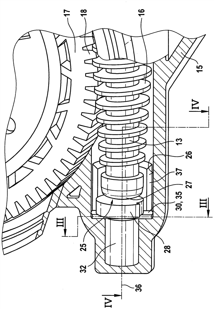
[0023] exist figure 1 The variable speed drive 10 shown in is a component of a convenience drive in a motor vehicle. A convenience drive is understood by way of example and without limitation to be a window lift drive, a sliding roof drive or the like, in which the element to be adjusted (window pane, sliding roof, etc.) is at least To move or manipulate indirectly.

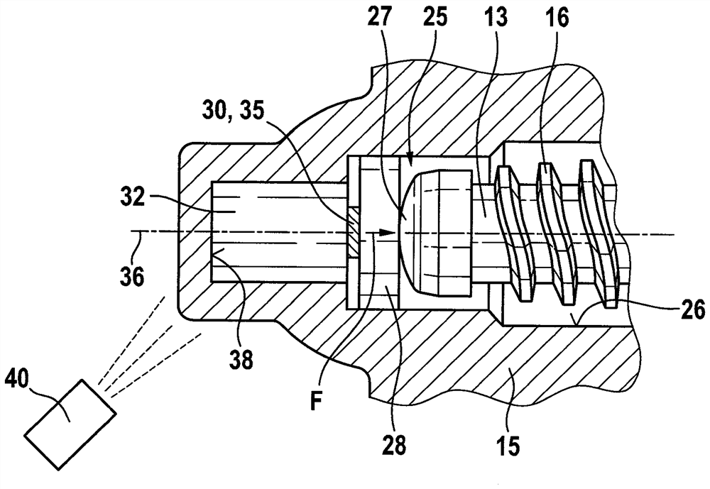
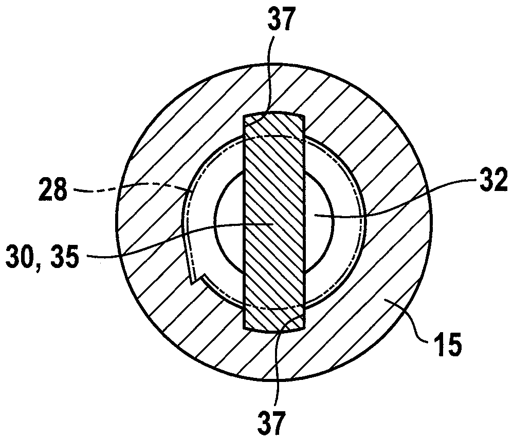
[0024] The variable speed drive 10 comprises an electric motor 12 arranged in a pole housing 11 , which protrudes via a section of an armature shaft 13 into a transmission housing 15 which is at least partially made of metal. The pole housing 11 is connected to the transmission housing 15 at the end in a conventional manner, for example by screwing.

[0025] The armature shaft 13 has, inside the transmission housing 15 , a toothing 16 designed as a helical toothing or a screw toothing, which meshes with a mating toothing 18 formed on the circumference of the spur gear 17 . The spur gear 17 is mounted rotatably...


PUM


Abstract

The invention relates to a variable-speed drive, in particular as part of a comfort drive in a motor vehicle, having an electric motor with an armature shaft with toothing formed on the armature shaft (13) which engages the driven The mating toothing of the element engages, wherein the armature shaft (13) cooperates at least indirectly with at least the housing element in the region of its two axial end regions for limiting the axial direction of the armature shaft in the longitudinal direction movement, at least an end portion of the armature shaft is arranged in abutting contact with the end face of the friction element. According to the invention, a temperature-dependent booster element is arranged on the side of the friction element opposite the end region, which is designed to generate a force acting in the longitudinal direction of the armature shaft when heated, between the end region and the Increased fit between friction elements.

Description

technical field [0001] The invention relates to a variable speed drive, in particular as part of a convenience drive in a motor vehicle. The invention also relates to a method for machining the variable speed drive. Background technique [0002] Such a variable speed drive is known from DE 10 2006 061 700 A1 of the applicant. Known variable speed drives are, for example, components of window lift drives, sliding roof drives or the like, in which the part to be adjusted (window glass, sliding roof, etc.) can move in different directions. The adjusting force required for this is generated by means of a variable speed drive, wherein the electric motor can be run in different directions. Restoring forces acting on the variable speed drive are caused by the components to be adjusted, which represent an axial force acting on the armature shaft via the meshing teeth between the speed change gear and the armature shaft. In order to reduce the commutation noise caused by the conta...

Claims


Application Information

Patent Timeline
Patent Type & Authority Patents(China)
IPC IPC(8): F16H57/028H02K7/116E05F15/697
CPCE05F15/697F16H57/028H02K7/116H02K5/24H02K7/081H02K7/1166H02K15/14
Inventor A.韦尔勒
Owner ROBERT BOSCH GMBH
Why Eureka
Try Eureka