
Female die, die and device for plate blank differential temperature drawing molding and drawing method

A differential temperature deep drawing and slab technology is applied in the fields of slab differential temperature deep drawing forming die, slab differential temperature deep drawing device, and slab differential temperature deep drawing die, which can solve the problem that the slab temperature cannot be further increased. Problems such as thermal deformation ability, low yield ratio and uniform deformation ability of slab, and difficulty in deep drawing can achieve the effect of reducing the ultimate drawing coefficient, reducing flow stress and reducing the number of deep drawing.

Inactive Publication Date: 2016-12-07
北京普惠三航科技有限公司
View PDF9 Cites 9 Cited by
  • Summary
  • Abstract
  • Description
  • Claims
  • Application Information

AI Technical Summary

Problems solved by technology

[0003] The quality of deep-drawn parts mainly depends on the key elements such as the material formability, forming process and forming die of the deep-drawn parts. For example, for low-carbon steel slabs, due to their low strength and hardness, they can be deep-drawn at room temperature Forming, but limited by the formability of the material of the slab itself, as the depth of drawing increases, the deformation ability of the slab will decrease, so the maximum depth of drawing is limited; and for the slab of duralumin alloy, Due to high strength and poor plasticity at room temperature, deep drawing at room temperature is very difficult
[0004] In order to reduce the deformation resistance of the higher-strength slab so that the higher-strength slab can be formed smoothly under the action of a smaller drawing force, an isothermal drawing process with a higher temperature can be considered. However, due to the higher temperature High isothermal drawing process, the lower the yield ratio and uniform deformation capacity of the slab, it is very easy to cause local flow of metal in the deformed area, resulting in drawing cracks, and the overall improvement of the slab drawing temperature cannot further improve the slab. Warm deformation ability of billet

Method used


Image

  • Female die, die and device for plate blank differential temperature drawing molding and drawing method
  • Female die, die and device for plate blank differential temperature drawing molding and drawing method
  • Female die, die and device for plate blank differential temperature drawing molding and drawing method

Examples


Embodiment Construction

[0041] Specific embodiments of the present invention will be described in detail below in conjunction with the accompanying drawings. It should be understood that the specific embodiments described here are only used to illustrate and explain the present invention, and are not intended to limit the present invention.

[0042] In the present invention, in the case of no contrary description, the used orientation words such as "up, down, left and right" usually refer to the up, down, left and right shown in the accompanying drawings, "inside and outside" Refers to the inside and outside relative to the outline of the part body.

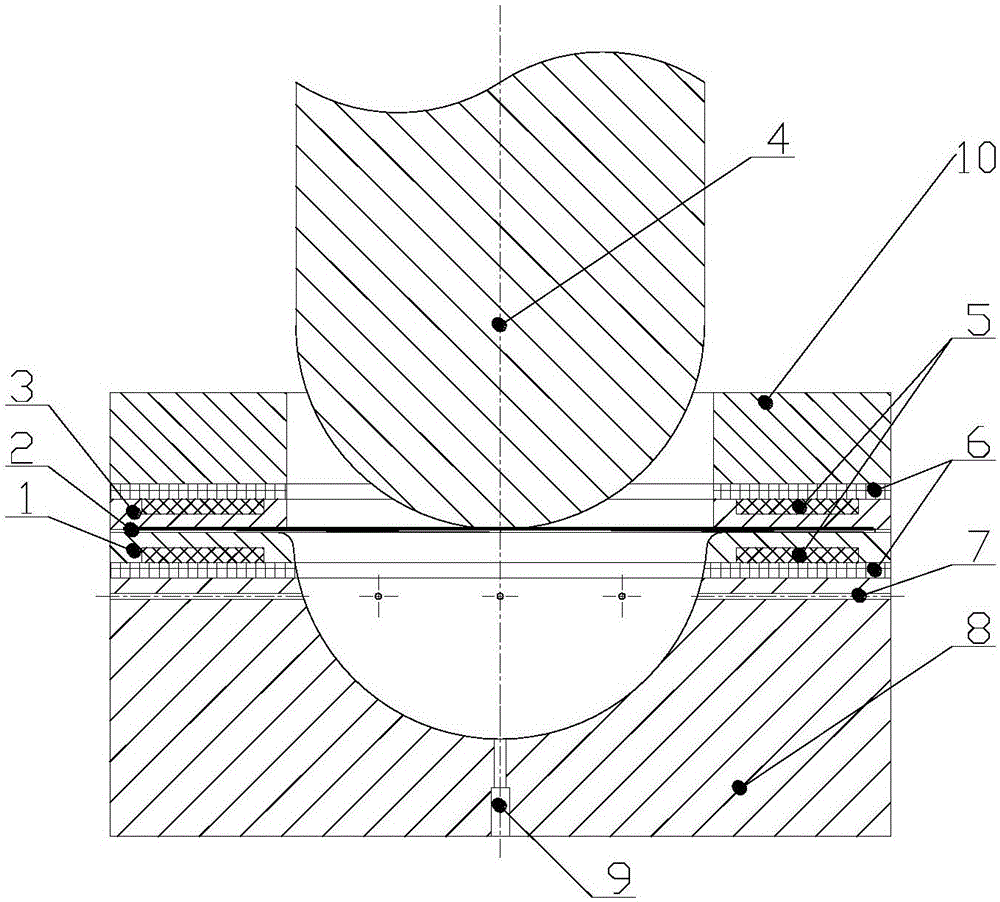
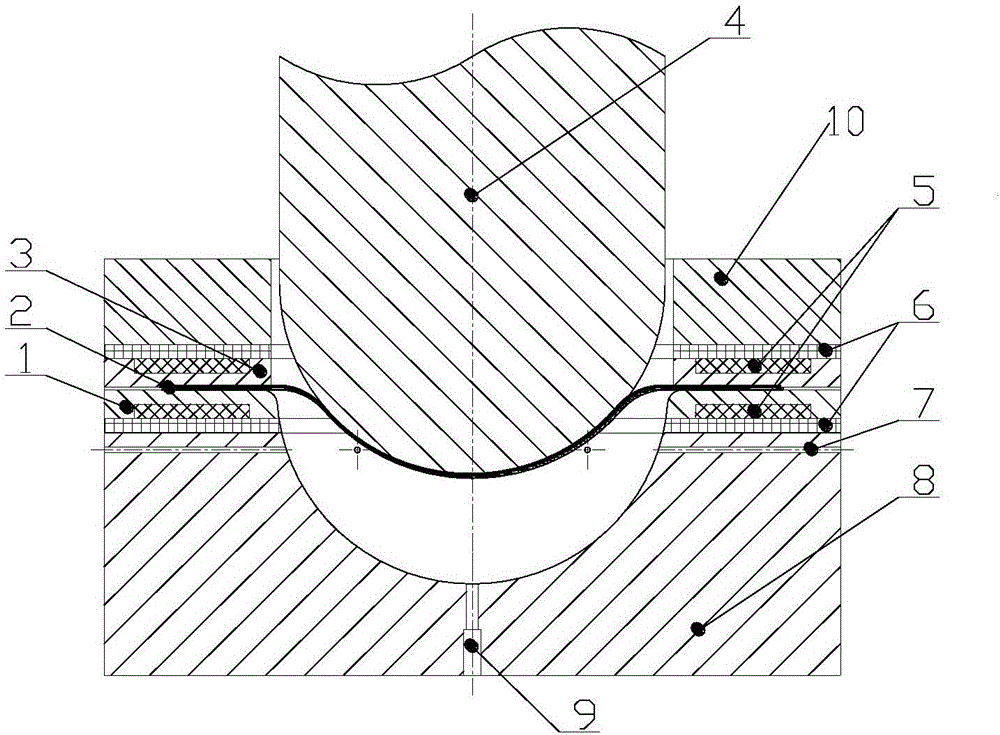
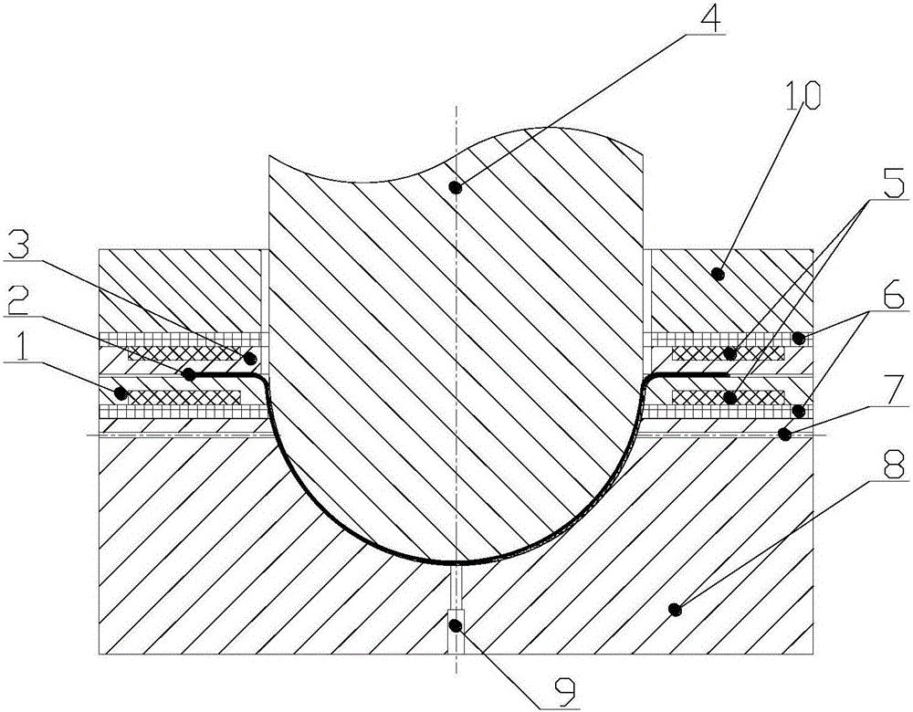
[0043] see Figure 1-Figure 3 , the first aspect of the embodiment of the present invention provides a die 8 for slab differential temperature deep drawing, the die 8 is provided with an air inlet for passing cooling gas into the groove of the die 8 channel 7, and an exhaust channel 9 for exhausting the cooling gas out of the groove. During the deep ...


PUM

PropertyMeasurementUnit
depthaaaaaaaaaa
depthaaaaaaaaaa
depthaaaaaaaaaa

Abstract

The invention relates to the technical field of metal machining, and discloses a female die, die and device for plate blank differential temperature drawing molding and a drawing method. The female die is provided with an air inlet passage used for leading cold air into a groove of the female die, and an exhaust passage used for exhausting the cold air out of the groove; and the die comprises a male die, an edge pressing device and the female die which are sequentially arranged in the vertical direction. The device comprises a pressing machine and the die. The drawing method includes the steps that firstly, a plate blank is tightly pressed between the edge pressing device and the female die; and secondly, the plate blank is drawn in the groove of the female die. By means of the technical scheme, the ultimate deformation degree of the plate blank can be improved, and the drawing performance of the plate blank is further improved.

Description

technical field [0001] The present invention relates to the field of metal processing, in particular to a die for slab differential temperature deep drawing, and further, the present invention also relates to a slab differential temperature deep drawing die, a slab differential temperature deep drawing device and A slab differential temperature deep drawing forming method. Background technique [0002] For plate parts characterized by thin walls and large surface areas, in order to process them into predetermined shape parts with thin walls and good mechanical properties, deep drawing is a feasible method. Taking the drawing of a flat slab into a large-sized thin-walled hemisphere as an example, at the beginning, the flat slab has a flat deformation area located under the blank holder, a free surface area located in the gap between the male and female dies, and a contact with the top of the punch. The plastic deformation zone; as the punch goes down, the free surface area o...

Claims


Application Information

Patent Timeline
Patent Type & Authority Applications(China)
IPC IPC(8): B21D37/10B21D37/16B21D22/22B21C51/00
CPCB21C51/00B21D22/22B21D37/10B21D37/16
Inventor 雷鹍刘新芹靳舜尧李波
Owner 北京普惠三航科技有限公司
Learn More