Numerically controlled grinder with rotatable grinding wheel head

A rotation angle, CNC grinding machine technology, applied in the direction of gear teeth, components with teeth, gear teeth manufacturing devices, etc., can solve the problems of complex spindle mechanism, complex adjustment process, and unfavorable mass production.

Inactive Publication Date: 2016-12-07
广东豪特曼机床股份有限公司
View PDF9 Cites 4 Cited by
  • Summary
  • Abstract
  • Description
  • Claims
  • Application Information

AI Technical Summary

Problems solved by technology

When grinding inclined workpieces, especially those with taper angles, it is necessary to manually adjust the angle of the grinding wheel. The adjustment process is complicated and delays working hours.
The grinding wheel is mostly repaired with a diamond repair pen, and the process of sand repair is slow, which is not conducive to large-scale production
The current grinding wheel is driven by an ordinary three-phase motor, and the mechanism of the main shaft is complicated. There will be slight vibration during the grinding process, which will affect the grinding accuracy.
At present, for thread grinding and gear grinding, special machine tools are required to complete the processing respectively, which leads to a large demand for equipment in the process of completing product processing, increases production costs, and affects processing efficiency

Method used


Image

  • Numerically controlled grinder with rotatable grinding wheel head
  • Numerically controlled grinder with rotatable grinding wheel head
  • Numerically controlled grinder with rotatable grinding wheel head

Examples


Embodiment Construction

[0017] The following will clearly and completely describe the technical solutions in the embodiments of the present invention with reference to the accompanying drawings in the embodiments of the present invention. Obviously, the described embodiments are only some, not all, embodiments of the present invention. Based on the embodiments of the present invention, all other embodiments obtained by persons of ordinary skill in the art without creative efforts fall within the protection scope of the present invention.

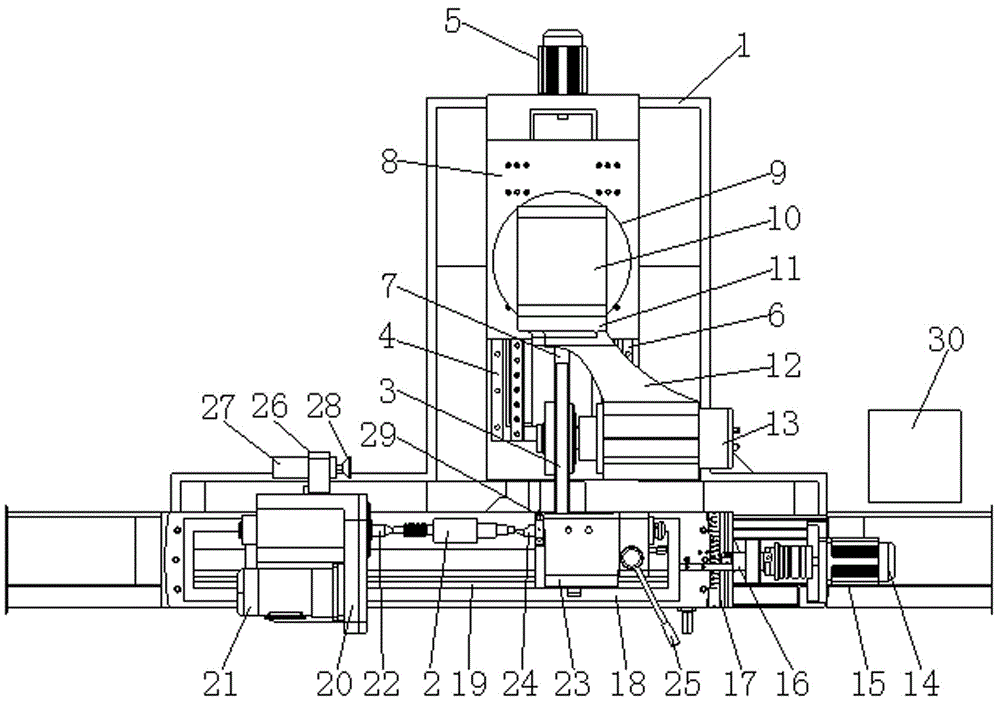
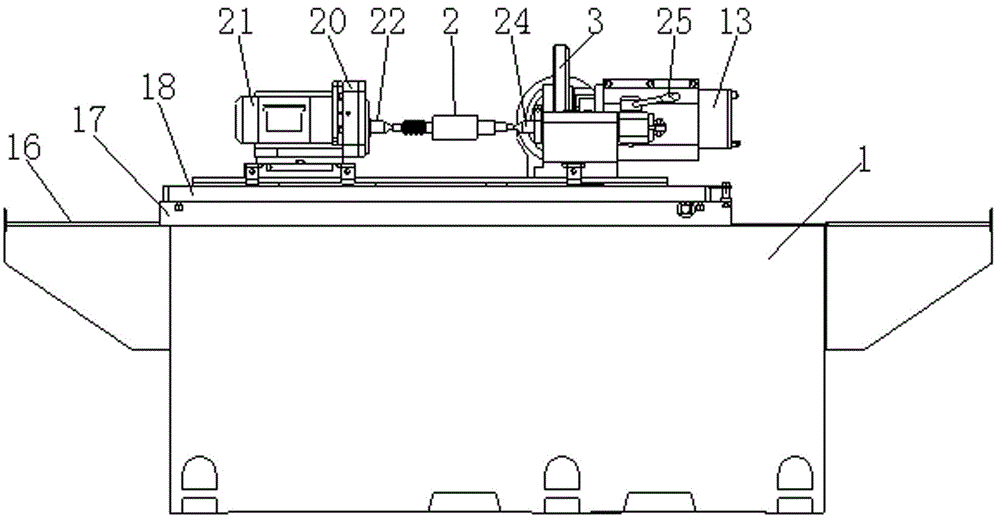
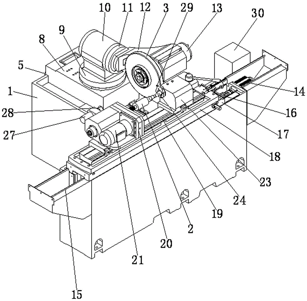
[0018] according to figure 1 , figure 2 and image 3 Shown, the processing mode of invention has following:

[0019] 1) Grinding the outer circle and the end face of the outer circle: the grinding wheel head base 4 on the main body 1 and the external control box 30, the first servo motor 5 on the grinding wheel head base 4 drives the first ball screw 7 to drive the skateboard fixing plate 8 Sliding along the first guide rail 6 toward the working head part, the ...


PUM


Abstract

The invention discloses a numerically controlled grinder with a rotatable grinding wheel head, which has the advantage that a grinding wheel can be tilted and turned to grind a thread and a tooth and can also swing left and right to grind a circular conical surface. According to the numerically controlled grinder, a first servo motor on a grinding wheel head base drives a sliding plate fixing plate to slide on a first guide rail via a first ball screw; a first direct-drive motor is mounted on the sliding plate fixing plate; a grinding wheel connecting seat is mounted on the first direct-drive motor; a second direct-drive motor is mounted on the grinding wheel connecting seat; a motorized spindle fixing seat is connected with the second direct-drive motor; a motorized spindle is mounted on the motorized spindle fixing seat; and the motorized spindle is connected with the grinding wheel to drive the grinding wheel to realize grinding machining. The first direct-drive motor and the second direct-drive motor can rotate respectively to control the grinding wheel on the motorized spindle to rotate left and right or tilt, and the grinding wheel can grind an external circular conical surface, gear or thread of a workpiece after being trimmed.

Description

technical field [0001] The invention relates to the technical field of machine tool structures, in particular to a numerical control grinding machine with a rotatable angle of a grinding wheel head. Background technique [0002] Grinding machines are commonly used in actual production and processing, and are usually used for grinding outer circular surfaces, inner hole surfaces, etc. When grinding inclined workpieces, especially those with taper angles, it is necessary to manually adjust the angle of the grinding wheel. The adjustment process is complicated and delays working hours. Diamond trimming pens are mostly used for sand repairing of grinding wheels, and the sand repairing process is slow, which is not conducive to large-scale production. The current grinding wheel is driven by an ordinary three-phase motor, and the mechanism of the main shaft is complicated. There will be slight vibration during the grinding process, which will affect the grinding accuracy. At pre...

Claims


Application Information

Patent Timeline
Patent Type & Authority Applications(China)
IPC IPC(8): B23G1/36B23F5/02B23F9/02B23F23/12
CPCB23G1/36B23F5/02B23F9/02B23F23/1262B23F23/1293
Inventor 曾俊
Owner 广东豪特曼机床股份有限公司
Why Eureka
Try Eureka