Workpiece clamping device of crystal bar orienting and material bonding machine

A workpiece clamp and sticker technology, applied in the mechanical field, can solve the problems of uneven pressure on the crystal rod, inaccurate sticking, and sticking angle error, so as to achieve intelligent and controllable pressure application, fast and convenient installation, and avoid errors. Effect

Inactive Publication Date: 2016-12-07
TAIZHUO SHUANGHUI MACHINERY EQUIP
View PDF11 Cites 3 Cited by
  • Summary
  • Abstract
  • Description
  • Claims
  • Application Information

AI Technical Summary

Problems solved by technology

[0004] The above-mentioned crystal adhesive machine and the crystal sticks in the prior art are all manually bonded on the bonding material board, but the artificial adhesive has the following defects: the manual method of pressing the artificial finger in the process of applying glue and water adhesive When the crystal rod is bonded to the bonding material plate, due to the uncontrollable pressure exerted artificially, the pressure on the crystal rod will be uneven, that is to say, in the process of artificial force, the originally adjusted bonding angle will appear relatively large. At the same time, the consistency of the bonding angle of a batch of crystal rods manually bonded is not high; therefore, due to many uncontrollable factors of human operation, the bonding material of the existing bonding machine is not accurate, which greatly affects the crystal. The accuracy of the subsequent cutting angle of the rod, thus affecting the quality of the subsequent wafer products

Method used


Image

  • Workpiece clamping device of crystal bar orienting and material bonding machine
  • Workpiece clamping device of crystal bar orienting and material bonding machine
  • Workpiece clamping device of crystal bar orienting and material bonding machine

Examples


Embodiment Construction

[0023] The following are specific embodiments of the present invention and in conjunction with the accompanying drawings, the technical solutions of the present invention are further described, but the present invention is not limited to these embodiments.

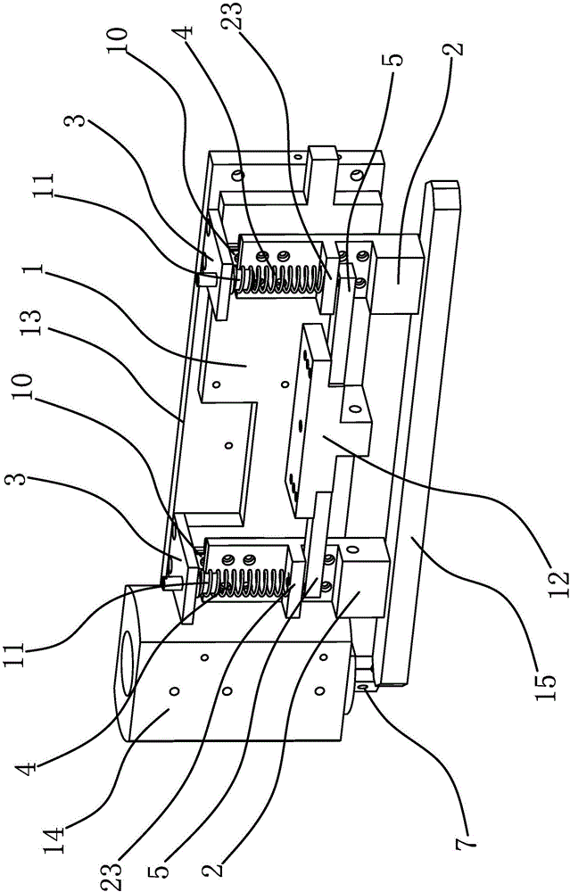
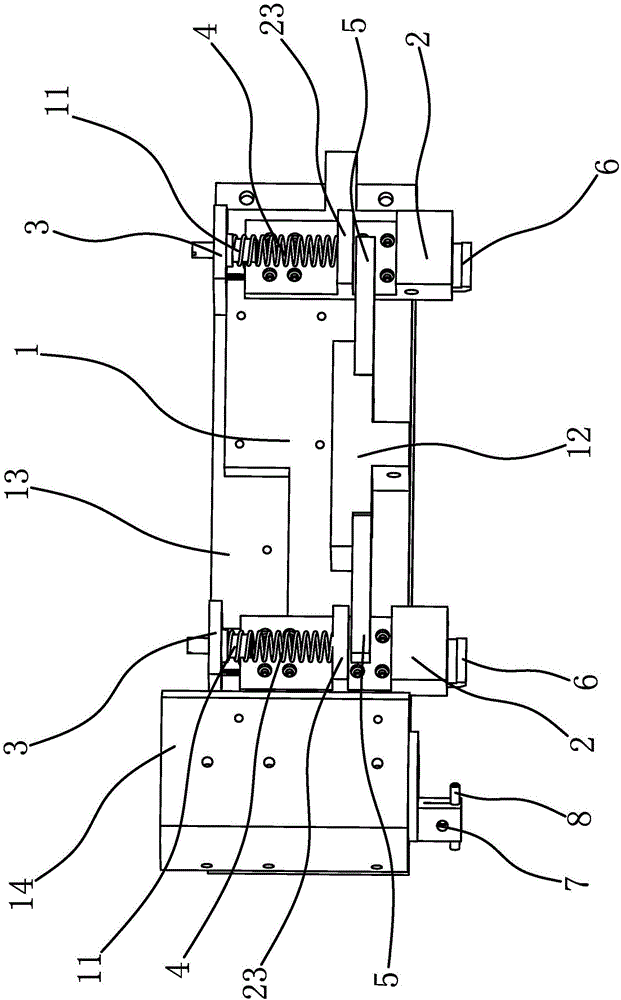
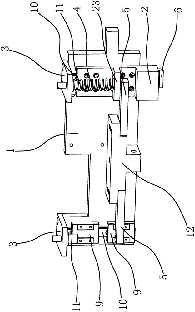
[0024] The workpiece clamping device of this crystal rod directional adhesive machine includes a clamp substrate 1, a vacuum suction head 2, a suction hole 2a, an air outlet 2b, a body 21, a suction head 22, a connecting portion 23, a spring pressure plate 3, a spring 4, a pressure Sensor 5, positioning side plate 6, thimble seat 7, thimble 8, slider 9, slide rail 10, spring pressure head 11, sensor mounting seat 12.

[0025] Specifically, as figure 1 As shown, the workpiece clamping device includes a fixture base plate 1 on which a strip-shaped vacuum suction head 2 capable of sliding in a vertical direction is slidably connected. There are two vacuum suction heads 2 and their positions correspond to the two ends of the ...


PUM


Abstract

The invention provides a workpiece clamping device of a crystal bar orienting and material bonding machine, and belongs to the technical field of machines. The workpiece clamping device solves the problem about how to make crystal bars bonded more accurately. The workpiece clamping device comprises a clamp base plate. The clamp base plate is in sliding connection with vacuum suction heads capable of sliding in the vertical direction. Suction holes used for adsorbing the crystal bars are formed in the bottoms of the vacuum suction heads. A spring is arranged between the clamp base plate and each vacuum suction head. The two ends of each spring abut against the clamp base plate and the corresponding vacuum suction head correspondingly. Pressure sensors are further fixedly connected to the clamp base plate. The detection ends of the pressure sensors make contact with and abut against the vacuum suction heads. When the workpiece clamping device clamps the crystal bars and the crystal bars are downwards pressed and bonded, the pressure applied by the workpiece clamping device can be monitored by the pressure sensors in real time, so that the applied pressure is intelligently controllable; and meanwhile, the pressure applying direction is fixed, so that the situation that an error happens to the originally-adjusted bonding angle in the crystal bar pressure applying bonding process is avoided, and crystal bar material bonding is more accurate.

Description

technical field [0001] The invention belongs to the technical field of machinery, and relates to a crystal rod directional bonding machine, in particular to a workpiece clamping device of the crystal rod directional bonding machine. Background technique [0002] As an important piezoelectric crystal material for manufacturing resonators such as crystal oscillators, crystal wafers are processed from grown crystal ingots of various specifications. Before crystal ingots are processed into wafers, they need to go through several processes of orientation, bonding and cutting. Among them, the crystal rod orientation bonding machine is a device that applies the principle of X-ray diffraction to orientate crystal rods and bond crystal rods by using angle measurement. [0003] For example, the Chinese patent [application number: 201520237731.8; authorized announcement number: CN204546806U] discloses a crystal bonding machine, including a frame, a cover plate, a goniometer, an X-ray ...

Claims


Application Information

Patent Timeline
Patent Type & Authority Applications(China)
IPC IPC(8): B28D5/00B28D7/00
CPCB28D5/0058
Inventor 朱史胜
Owner TAIZHUO SHUANGHUI MACHINERY EQUIP
Why Eureka
Try Eureka