
Conductive adhesive bonding

Inactive Publication Date: 2006-03-23
GM GLOBAL TECH OPERATIONS LLC
View PDF25 Cites 64 Cited by
  • Summary
  • Abstract
  • Description
  • Claims
  • Application Information

AI Technical Summary

Benefits of technology

[0008] Thus, the selection of the metal particles normally depends on the material of the bipolar plate. For example, when ferrous metal bipolar sheets are to be bonded, nickel-phosphorus particles or alloy particles from systems that form eutectic alloys with iron, such as the iron-phosphorus, iron-carbon or iron-silicon systems are suitable. Either nickel-phosphorus or the eutectic ferrous alloys or intermetallics are susceptible to melting, wetting and flowing against stainless steel sheet material. After wetting the facing sheet surfaces, the metallic element containing droplets re-solidify to form many conductive paths from sheet to sheet and decrease the electrical resistance inherent in the adhesive bond.

Problems solved by technology

Either nickel-phosphorus or the eutectic ferrous alloys or intermetallics are susceptible to melting, wetting and flowing against stainless steel sheet material.
After wetting the facing sheet surfaces, the metallic element containing droplets re-solidify to form many conductive paths from sheet to sheet and decrease the electrical resistance inherent in the adhesive bond.

Method used

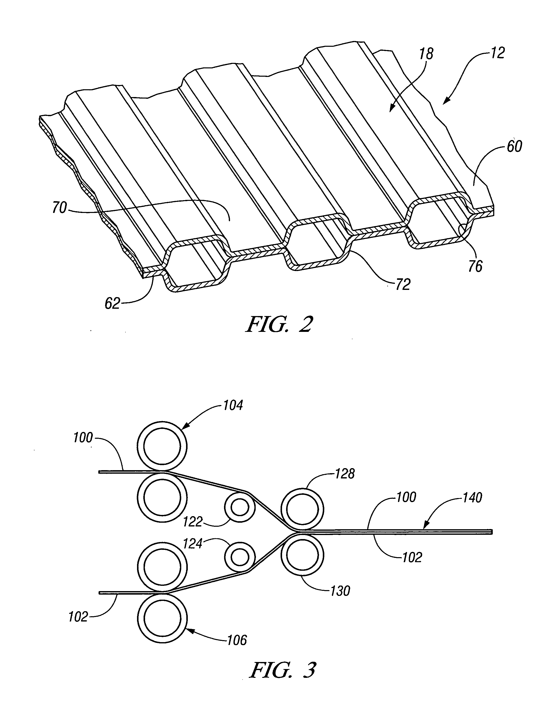

Image

  • Conductive adhesive bonding
  • Conductive adhesive bonding
  • Conductive adhesive bonding

Examples


Embodiment Construction

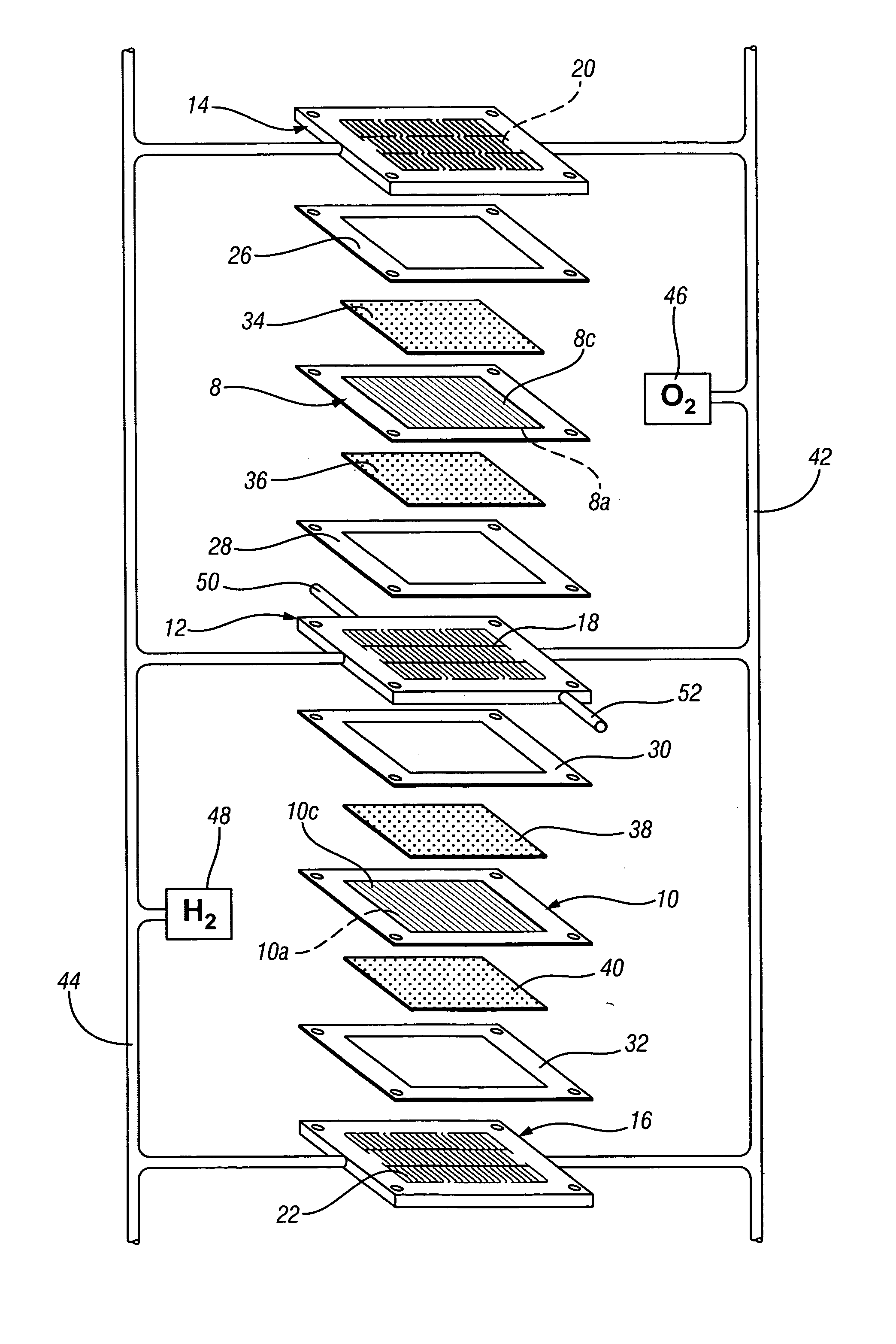
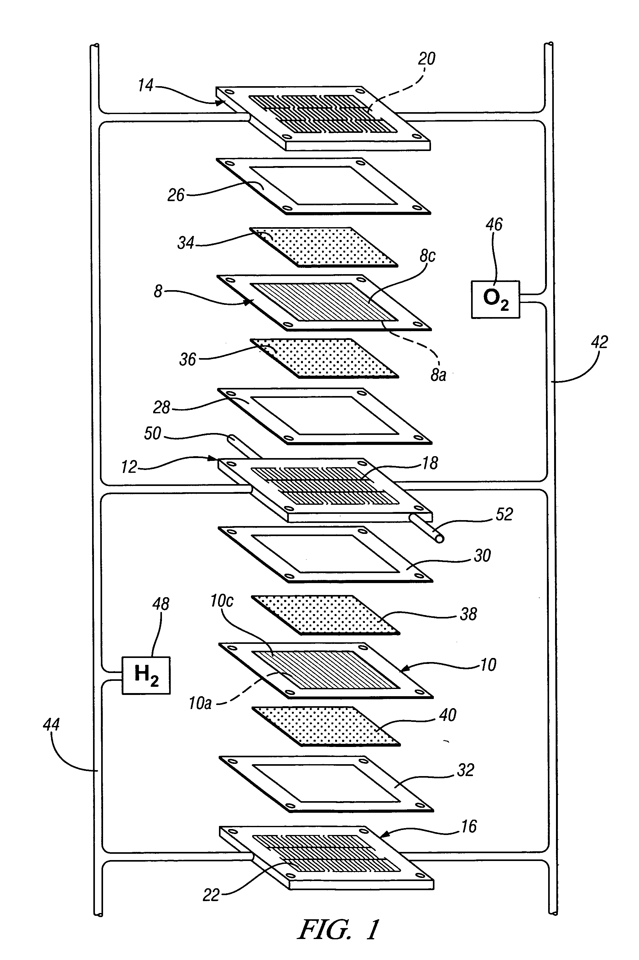
[0019]FIG. 1 schematically depicts a representative partial fuel cell stack having a pair of membrane-electrode-assemblies (MEAs) 8, 10 separated from each other by a non-porous, electrically-conductive bipolar plate 12. Each of the MEAs 8, 10 have a cathode face 8c, 10c and an anode face 8a, 10a. The MEAs 8, 10, and bipolar plate 12, are stacked together between non-porous, electrically-conductive, liquid-cooled bipolar plates 14, 16. The bipolar plates 12, 14 and 16 each include flow fields 18, 20 and 22 having a plurality of flow channels formed in the faces of the plates for distributing fuel and oxidant gases (e.g., H2 and O2) to the reactive faces of the MEAs 8, 10. Nonconductive gaskets or seals 26, 28, 30 and 32 provide a seal and electrical insulation between the several plates of the fuel cell stack.

[0020] Porous, gas permeable, electrically conductive sheets 34, 36, 38 and 40 press up against the electrode faces of the MEAs 8, 10 and serve as primary current collectors f...


PUM

PropertyMeasurementUnit
Lengthaaaaaaaaaa
Thicknessaaaaaaaaaa
Electrical conductivityaaaaaaaaaa

Abstract

Electrically conductive workpieces with facing surfaces are bonded with an adhesive that is filled with conductive metal particles that are reactive with the surfaces of the workpieces. In the bonding process the surfaces are coated with the adhesive, pressed together and an electric current passed between them to momentarily melt the conductive particles. The molten droplets agglomerate and wet the facing surfaces. When the molten clusters re-solidify, electrically conductive paths are formed between the workpieces. For example, the practice is useful for bonding ferrous-based or aluminum-based alloy sheets, strips or plates in making products such as bipolar plates for fuel cells.

Description

TECHNICAL FIELD [0001] This invention pertains generally to adhesive bonding of facing surfaces of electrically conductive workpieces to improve electrical conductivity through the insulating adhesive layer. More specifically this invention pertains to the use of an adhesive that is filled with conductive metal particles that are momentarily melted during the bonding process to wet the facing surfaces and, upon re-solidification, form many conductive paths between them. As an example, the method is applicable to bond the facing sheets of bipolar current collector plates for fuel cells to improve conductivity within these fuel cell elements. BACKGROUND OF THE INVENTION [0002] Fuel cells that electrochemically combine hydrogen and oxygen are presently being developed and used for production of electric power in stationary and mobile applications. These power sources comprise a stack of individual cell elements that are designed to deliver a power requirement at a specified voltage. Th...

Claims


Application Information

Patent Timeline
IPC IPC(8): B32B37/00B29C65/00
CPCB32B37/12B32B2305/30B32B2457/18C09J5/06C09J9/02Y10T156/1016C09J2400/163H01B1/22C09J2201/602B32B2307/202C09J2301/314
Inventor SIGLER, DAVID R.SCHROTH, JAMES G.
Owner GM GLOBAL TECH OPERATIONS LLC
Learn More