Linear robotic arm and robot collaborative billet removal system

A technology of robot and robot arm, applied in the field of linear robot arm and robot collaborative preform removal system, which can solve the problems of unguaranteed preform quality, high preform drop times, high preform drop height, etc., to increase the processing range, Compact structure and high motor utilization efficiency

Active Publication Date: 2018-01-30
广州一道注塑机械股份有限公司
View PDF6 Cites 0 Cited by
  • Summary
  • Abstract
  • Description
  • Claims
  • Application Information

AI Technical Summary

Problems solved by technology

This structure has the defects of large preform drop height, large impact, and loud noise. The more cavities, the greater the weight of the preform, and the longer the length of the preform, the more obvious the defects exposed, which are mainly reflected in the following aspects :
[0003] First, the more preforms in the mold cavity, the longer the preform length, the larger the overall size of the manipulator take-out structure, the larger the required rotation radius, and the greater the height of the preform falling to the conveyor belt surface, which will easily cause the preform to fall to the conveyor belt surface. The drop damage will affect the quality of the preform
[0004] Second, the greater the weight of the preform and the longer the length of the preform, the greater the deformation of the preform when it falls, and even the preforms collide with each other when they fall to the conveyor belt, resulting in secondary damage to the preform;
During this conveying process, the preforms fall many times, and the impact force is large, and the quality of the preforms is not guaranteed.
[0006] Fourth, there is a lot of noise when the preform falls

Method used


Image

  • Linear robotic arm and robot collaborative billet removal system
  • Linear robotic arm and robot collaborative billet removal system
  • Linear robotic arm and robot collaborative billet removal system

Examples


Embodiment Construction

[0030] The idea, specific structure and technical effects of the present invention will be clearly and completely described below in conjunction with the embodiments and accompanying drawings, so as to fully understand the purpose, features and effects of the present invention. Apparently, the described embodiments are only some of the embodiments of the present invention, rather than all of them. Based on the embodiments of the present invention, other embodiments obtained by those skilled in the art without creative efforts belong to The protection scope of the present invention. In addition, all the connection / connection relationships mentioned in this article do not refer to the direct connection of components, but mean that a better connection structure can be formed by adding or reducing connection accessories according to specific implementation conditions.

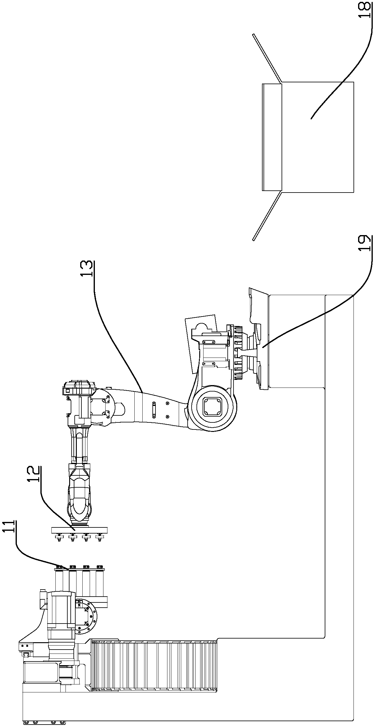
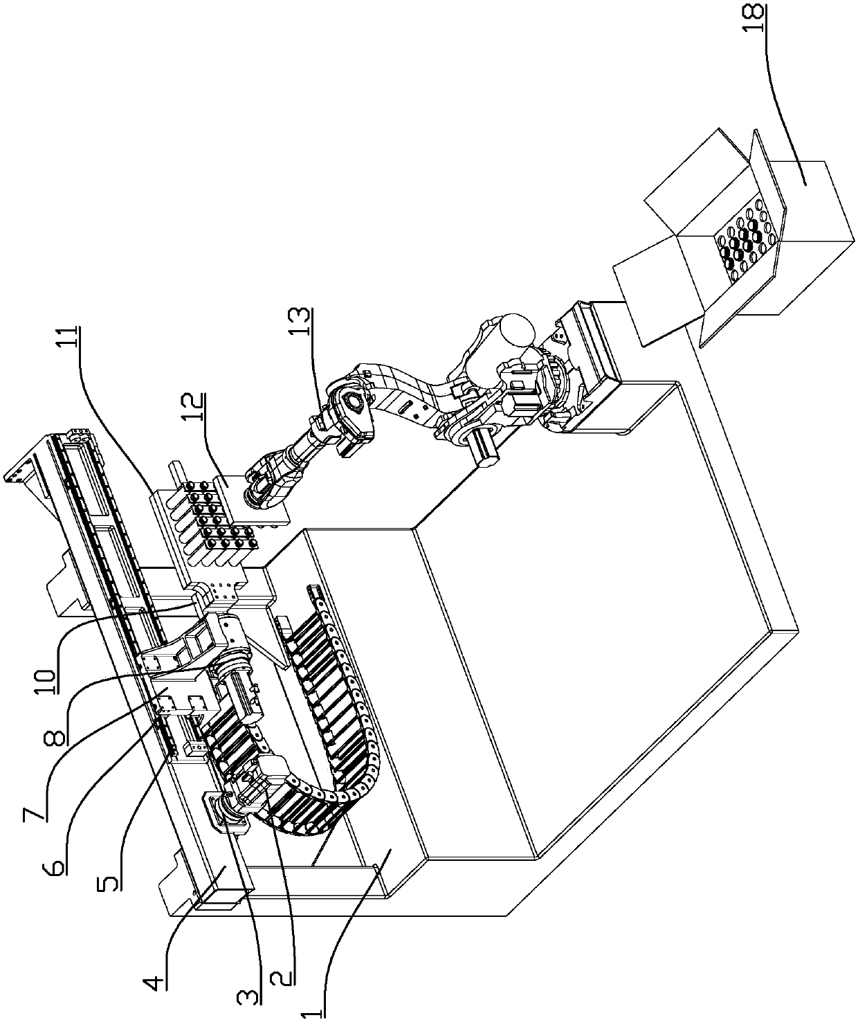
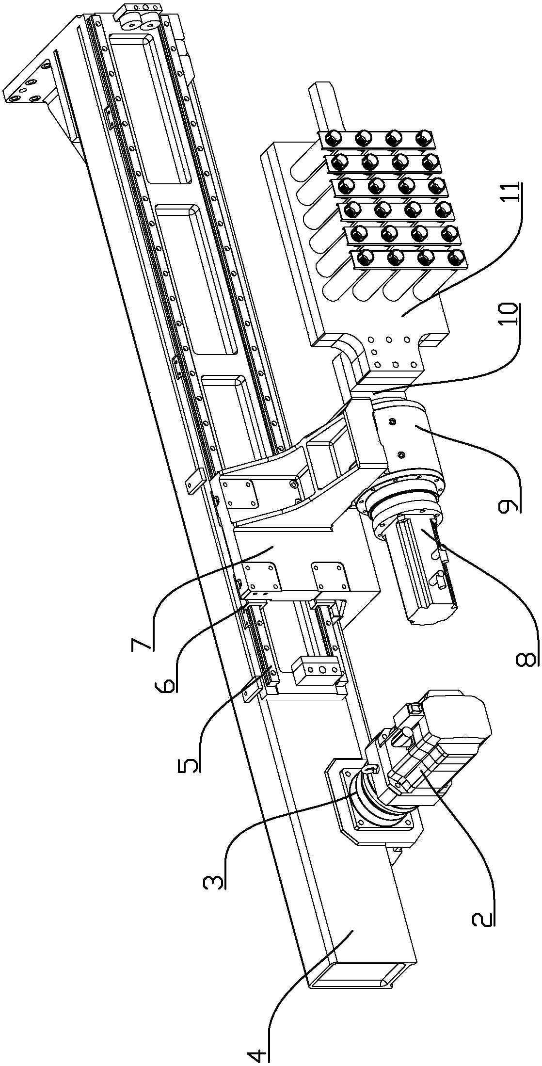
[0031] Such as figure 1 The shown linear robot arm and robot cooperative billet removal system is composed of a...


PUM


Abstract

The invention discloses a linear robot arm and a robot cooperative blanking system, including a robot unloading system, a frame and a linear robotic arm blanking system. The linear robotic arm blanking system includes a beam, a servo motor, two guide rails, and two sliders , slider seat, transmission mechanism, overturning motor and blank take-off plate, the robot blank unloading system includes the robot and the blank unloading plate installed on the terminal shaft of the robot, the blank unloading position and the blank take-off position are set on the guide rail, the servo motor drives the slide The block reciprocates between the blank unloading position and the blank picking position. When the slider is at the blank unloading position, after the blank unloading plate and the blank taking plate are arranged in parallel to form a blank unloading space between the two, the turning motor drives the blank picking work. The end is turned from horizontal to vertical downward, and the unloading plate is turned over with the blank plate. The drop height of the preform is small, and the instantaneous impact force on the preform is small, which avoids the drop deformation of the preform and effectively guarantees the quality of the preform, especially suitable for the working conditions of heavy weight and long length of the preform.

Description

technical field [0001] The invention relates to a preform removal device of a multi-cavity bottle preform injection molding machine, in particular to a linear robot arm and robot cooperative preform removal system. Background technique [0002] With the continuous improvement of the production efficiency of PET (PET is the English abbreviation of Polyethylene terephthalate, the Chinese name is polyethylene terephthalate, referred to as: polyester) preform injection molding machine, it is required Quality and efficiency are also improved accordingly. It is mainly reflected in the fact that the manipulator unloads more preforms at a time, takes less time, has high control over the quality of preforms, and has a good shape of preforms. The existing preform extraction system currently adopts a side-entry manipulator structure. After the manipulator enters the mold to take out the preform, it rotates to a horizontal position, and the preform is ejected by the cylinder. On the s...

Claims


Application Information

Patent Timeline
Patent Type & Authority Patents(China)
IPC IPC(8): B29C45/42B29C45/17
CPCB29C45/1769B29C45/42B29C2045/177
Inventor 易恒光徐志江游强陈琴
Owner 广州一道注塑机械股份有限公司
Why Eureka
Try Eureka