Method and system for improving performance of metallurgical slag dry-process pelletizing device

A dry granulation and slag granulation technology, which is applied in the field of metallurgical energy saving, can solve the problems of agglomeration of plates and slag particles adhering to the wall, and achieve the effect of avoiding adhesion or agglomeration of plates.

Active Publication Date: 2016-12-07
CHONGQING CISDI THERMAL & ENVIRONMENTAL ENG CO LTD
View PDF5 Cites 3 Cited by
  • Summary
  • Abstract
  • Description
  • Claims
  • Application Information

AI Technical Summary

Problems solved by technology

[0004] In view of this, the object of the present invention is to provide a method and system for improving the performance of a metallurgical slag d

Method used


Image

  • Method and system for improving performance of metallurgical slag dry-process pelletizing device
  • Method and system for improving performance of metallurgical slag dry-process pelletizing device
  • Method and system for improving performance of metallurgical slag dry-process pelletizing device

Examples


Embodiment 1

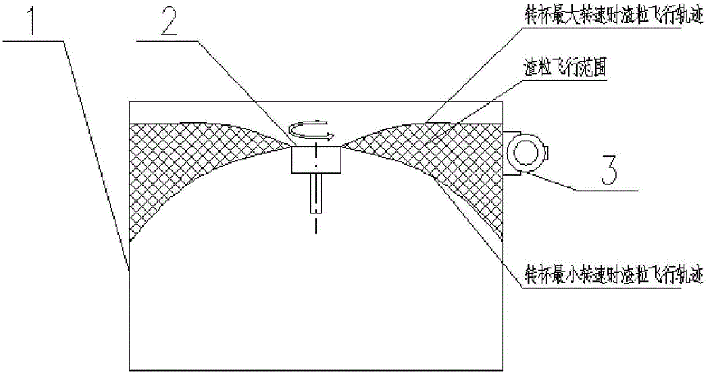
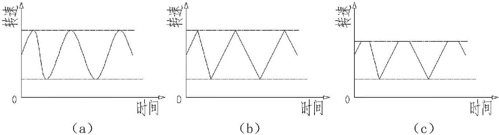
[0038] Such as Figure 1-2 , 5, because the flying speed of the slag particles is related to the rotating speed of the rotor, the flying speed of the slag particles is lower when the rotating cup is slow, and the flying speed of the slag particles is higher when the rotating cup is fast, so if the slag particles only keep constant When the speed hits the wall surface of the slag particle impact area of ​​the slag receiving chamber, because too many slag particles continue to hit the same position on the inner wall surface, it is easy to cause the slag particles to stick and harden into blocks on the inner wall surface. Therefore, in this embodiment The characteristic is that the rotational speed of the rotor is not constant. Concretely, this method utilizes the rotational speed of the rotor to change periodically with time to carry out the slag granulation, including the following sub-steps: first, collect the minimum rotational speed and the maximum rotational speed of the ro...

Embodiment 2

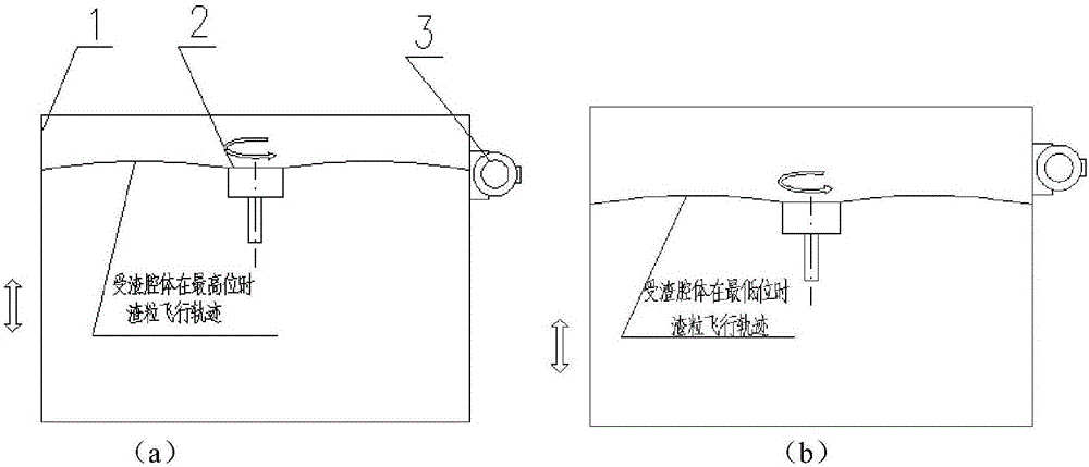
[0041] Such as Figure 3-5 As shown, since the slag particle bonding is related to the effective area of ​​the wall surface of the slag particle impact area of ​​the slag receiving cavity, that is, the half of the wall surface of the slag receiving cavity slag particle impact area usually adopts a water-cooled structure, and the slag particles hit the slag receiving cavity After the body slag particles hit the wall of the area, a certain cooling effect will be obtained. In this way, if the slag particles hit only one part of the inner wall surface, the temperature of the slag particles will drop slowly, which will easily cause the slag particles to stick and harden on the inner wall surface. Therefore, this embodiment is characterized in that the vertical height position of the slag receiving cavity is not constant. Specifically, this method uses the vertical height position of the slag receiving chamber to change periodically with time to carry out slag granulation, including...

Embodiment 3

[0044] This embodiment is to combine the two methods of embodiment 1 and embodiment 2 at the same time, that is, to make the rotation speed of the rotor 2 and the vertical height position of the slag receiving chamber 1 not constant at the same time, and the specific details will not be repeated. In this way, the slag particles can also obtain different impact positions on the slag receiving chamber, so the contact point of the slag particles on the wall surface of the slag receiving chamber slag particle impact area will also change with the rotation speed of the rotor and the slag receiving chamber. Periodic changes occur due to changes in the vertical height position of the body, thus forming a relatively dispersed impact zone. In this way, since the impact points of the slag particles are scattered, the phenomenon of bonding and agglomeration is not easy to occur.


PUM


Abstract

The invention discloses a method and a system for improving the performance of a metallurgical slag dry-process pelletizing device and belongs to the technical field of metallurgy energy saving. The pelletizing device comprises a slag collecting cavity vertically arranged and a rotating cup located in the center in a hollow cavity of the slag collecting cavity. According to the method, slag pelletization is carried out by utilizing the periodical variation of the rotating speed of the rotating cup and/or the vertical height of the slag collecting cavity with time. The system comprises the pelletizing device, a variable-frequency motor, an electric-hydraulic push rod and a controller, wherein the variable-frequency motor is fixedly connected with the rotating cup through a vertical rotating shaft, the electric-hydraulic push rod is fixedly connected with the slag collecting cavity, and the controller and the variable-frequency motor are electrically connected with the electric-hydraulic push rod. When slag pelletization is carried out, the positions that pelletized slag particles hit the wall surface of the slag collecting cavity periodically vary, so that bonding or hardening caused by the concentrated hitting of the slag particles on the wall surface is effectively avoided.

Description

technical field [0001] The invention belongs to the technical field of metallurgy and energy saving, and in particular relates to a method and system for improving the performance of a metallurgical slag dry granulation device. Background technique [0002] According to the "Basic Situation of Comprehensive Utilization of Iron and Steel Slag in 2012" issued by the Metallurgical Slag Development and Utilization Working Committee of China Scrap Iron and Steel Application Association, the production of blast furnace slag in my country in 2012 was 220 million tons. The discharge temperature of blast furnace slag is above 1400°C, which is high-quality heat energy. Calculated by the sensible heat of 1.8GJ per ton of slag, the available heat energy of blast furnace slag per year is 3.96×10 8 GJ, equivalent to 13.53 million tons of standard coal. However, at present, blast furnace slag in my country is mainly treated by water quenching, which not only wastes water resources, but al...

Claims


Application Information

Patent Timeline
IPC IPC(8): C21B3/06
CPCC21B3/06Y02W30/50
Inventor 陈君张道明
Owner CHONGQING CISDI THERMAL & ENVIRONMENTAL ENG CO LTD
Why Eureka
Try Eureka