Working head applicable to laser leveling machine

A technology of laser leveling machine and working head, which is applied in the direction of roads, road repairs, roads, etc., and can solve the problems of low construction precision, high labor intensity, and difficulty in guaranteeing construction quality

Active Publication Date: 2016-12-07
SHANDONG VANSE MECHANICAL TECH CO LTD
View PDF6 Cites 2 Cited by
  • Summary
  • Abstract
  • Description
  • Claims
  • Application Information

AI Technical Summary

Problems solved by technology

[0003] At present, in the construction process of roads and plant floors, it is necessary to manually tamp the ground and then pour the concrete mixture into the construction site through machinery, then spread the concrete mixture repeatedly manually to form a relatively smooth surface, and then manually or mechanically wipe Flat, when manually smoothed, the construction labor intensity is high and the efficiency is low. When mechanically smoothed, due to the uneven construction ground, it is easy to cause low construction accuracy and difficult to guarantee the construction quality

Method used


Image

  • Working head applicable to laser leveling machine
  • Working head applicable to laser leveling machine
  • Working head applicable to laser leveling machine

Examples


Embodiment Construction

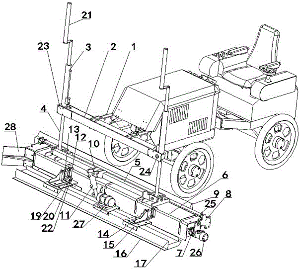
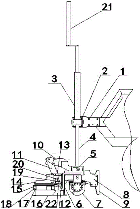
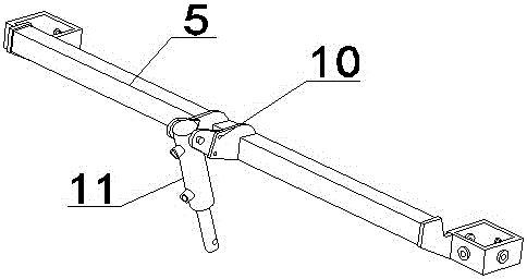
[0018] according to Figures 1 to 4 As shown, the present invention relates to a working head for a laser leveling machine, which includes two working head mounting frames 1 arranged in parallel at the front end of the laser leveling machine, the working head mounting frame 1 and a mounting frame at both ends The middle part of the beam 2 is connected, the mounting frame at the left end of the beam 2 can be a fixed leveling cylinder 23, and the mounting frame at the right end of the beam 2 can be a swinging leveling cylinder 24; each of the two ends of the beam 2 Telescopic oil cylinders 3 are respectively installed on the tops of each of the installation frames, and a sensor receiving installation frame 21 is connected to the top of each of the telescopic oil cylinders 3, and connecting rods are respectively installed on the bottom of each of the installation frames at both ends of the crossbeam 2. 4. The lower end of each connecting rod 4 is respectively installed in the fix...


PUM


Abstract

The invention discloses a working head applicable to a laser leveling machine. The working head applicable to the laser leveling machine comprises two working head mounting brackets and a beam used for being connected with the two working head mounting brackets. Telescopic cylinders and connecting rods are mounted at the upper parts and the lower parts of the two ends of the beam, the lower ends of the connecting rods are arranged in permanent seats of a movable joint holder, the middle of the movable joint holder is hinged to a tilting cylinder through a tilting cylinder holder, a stranding cage shell is mounted at the bottoms of the permanent seats of the movable joint holder, the other end of the tilting cylinder is connected to the outer wall of the stranding cage shell, mounting bases are arranged on the both sides of the stranding cage shell, the outer sides of the mounting bases are connected with two traction joint base plates through two traction joint shafts, the bottoms of the two traction joint base plates are fixedly connected to the upper part of an ironing plate through two connection plates, a stranding cage is mounted between stranding cage mounting wallboards at the bottom of the stranding cage shell, and a scraper blade is mounted at the rears of the two ends of the stranding cage shell through a scraper blade holder. By adopting the structure, the effects of being high in mechanization degree, high in efficiency, and capable of improving the construction quality and construction precision, and lowering the labor intensity are achieved.

Description

[0001] This application is a divisional application of the invention patent application with the application number: 201510318387X and the name: "Automatic Leveling Working Head of Laser Leveling Machine". The original application date is: June 11, 2015. technical field [0002] The invention relates to a concrete leveling device, in particular to a laser leveling machine working head used on a laser concrete leveling machine. Background technique [0003] At present, in the construction process of roads and plant floors, it is necessary to manually tamp the ground and then pour the concrete mixture into the construction site through machinery, then spread the concrete mixture repeatedly manually to form a relatively smooth surface, and then manually or mechanically wipe Flat, manual smoothing, the construction labor intensity is high, low efficiency, mechanical smoothing, due to uneven construction ground, easy to cause low construction accuracy, construction quality is diff...

Claims


Application Information

Patent Timeline
Patent Type & Authority Applications(China)
IPC IPC(8): E01C19/42E04F21/24
Inventor 朱军
Owner SHANDONG VANSE MECHANICAL TECH CO LTD
Why Eureka
Try Eureka