Valve state on-line monitoring system and working method thereof

A monitoring system and valve technology, applied in the direction of measuring devices, instruments, etc., can solve the problems of inability to establish parameter relationships, deviations, inability to identify and judge faulty valves, and achieve the effects of high reliability, compact structure and convenient use.

Active Publication Date: 2016-12-07
YANGZHOU ELECTRIC POWER EQUIP MFG FACTORY CO LTD
View PDF7 Cites 7 Cited by
  • Summary
  • Abstract
  • Description
  • Claims
  • Application Information

AI Technical Summary

Problems solved by technology

[0002] At present, due to testing equipment, users do not have accurate data support for the online operation status of the valve. The design and manufacture of valves are often carried out based on theoretical calculations and experience, which has a large deviation from the actual working conditions.
The valve state characterization parameters: torque, valve position, and pressure are often tested on different instruments, and the relationship between parameters cannot be established. At the same time, it is impossible to identify and judge faulty valves, so as to propose maintenance suggestions

Method used


Image

  • Valve state on-line monitoring system and working method thereof
  • Valve state on-line monitoring system and working method thereof
  • Valve state on-line monitoring system and working method thereof

Examples


Embodiment Construction

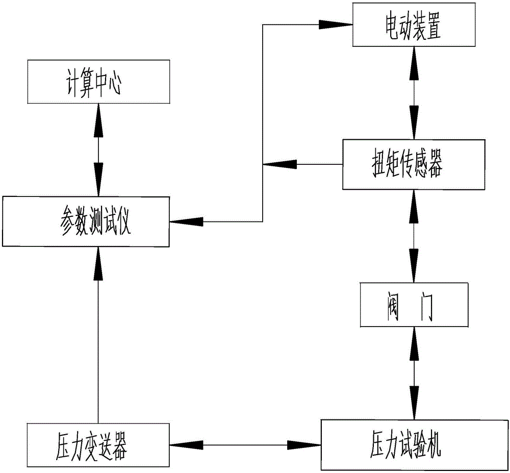
[0038] The present invention as Figure 1-3 As shown, including computing center, parameter tester, pressure transmitter, pressure testing machine, electric device and torque sensor;

[0039] The electric device is connected to the valve and used to drive the valve to open or close;

[0040] The torque sensor is connected between the electric device and the valve, and is used to collect the current torque of the valve;

[0041] The pressure testing machine is connected to the valve and used to apply external pressure to the valve;

[0042] The pressure transmitter is connected with the pressure testing machine, and is used to measure the current working pressure on the valve and convert it into a current signal;

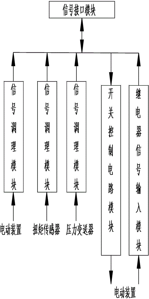
[0043] The pressure transmitter, torque sensor, and electric device are all connected to the computing center through a parameter tester, and the parameter tester is used for mutual conversion of current signals and voltage signals.

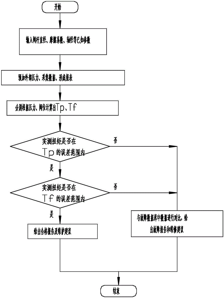
[0044] The calculation center...


PUM


Abstract

The invention discloses a valve state on-line monitoring system and a working method thereof. The invention relates to the field of industry process control and detection, and in particular to improvements of technology of valve state on-line monitoring and fault diagnosis. The valve state on-line monitoring system has exquisite structure, is easy to use and has high reliability, and can use valve position (i.e., valve caliber and opening amount of a valve gate) and valve pressure to calculate a theoretical torque so as to compare the theoretical torque and actual torque and finally provide accurate determination of the state of the valve. An electric apparatus is connected to the valve, and is intended for driving the valve to perform opening and closing movement. A torque sensor is connected between the electric apparatus and the valve, and is intended for acquiring the current torque of the valve. A pressure transmitter is connected to a compression testing machine, and is intended for measuring current working pressure of the valve, and converts the pressure to a current signal. According to the invention, the system as a whole is characterized by exquisite structure, easy usage and high reliability.

Description

technical field [0001] The invention relates to the field of industrial process control and detection, in particular to the technical improvement of on-line monitoring and fault diagnosis of valve states. Background technique [0002] At present, due to the testing equipment, the users do not have accurate data support for the online operation status of the valve. The design and manufacture of valves are often carried out based on theoretical calculations and experience, which has a large deviation from the actual working conditions. The valve status parameters: torque, valve position, and pressure are often tested on different instruments, and the relationship between parameters cannot be established. At the same time, it is impossible to identify and judge faulty valves, so as to propose maintenance suggestions. Contents of the invention [0003] In view of the above problems, the present invention proposes a compact structure, easy to use and high reliability, which can...

Claims


Application Information

Patent Timeline
Patent Type & Authority Applications(China)
IPC IPC(8): G01D21/02
CPCG01D21/02
Inventor 陈久松罗兆荣徐文才朱政张宇张建祥褚俊胡世鹏
Owner YANGZHOU ELECTRIC POWER EQUIP MFG FACTORY CO LTD
Why Eureka
Try Eureka