Bi-mode full polarization imaging polarization measurement method

A full-polarization, dual-mode technology, applied in the field of dual-mode full-polarization imaging deviation measurement, can solve the problems of low signal-to-noise ratio, low spatial resolution, subsequent utilization of unfavorable polarization information, etc., to improve spatial resolution and eliminate crosstalk Effect

Active Publication Date: 2016-12-07
GUANGXI TEACHERS EDUCATION UNIV
View PDF4 Cites 10 Cited by
  • Summary
  • Abstract
  • Description
  • Claims
  • Application Information

AI Technical Summary

Problems solved by technology

The disadvantage of this method is that S 2 and S 3 The modulation factor is only S 1 half of , resulting in the inversion of S at the same noise level 2 and S 3 The signal-to-noise ratio is significantly lower than that of S 1 , which will result in the S 2 or S 3 The polarization parameters calculated by the components (such as polarization angle θ=[arctan(S 2 / S 1 )] / 2, polarization azimuth angle etc.) The signal-to-noise ratio is not high, which is not conducive to the subsequent use of polarization information; the polarization parameter S 0 channel has crosstalk to other channels, and S 0 low spatial resolution

Method used


Image

  • Bi-mode full polarization imaging polarization measurement method
  • Bi-mode full polarization imaging polarization measurement method
  • Bi-mode full polarization imaging polarization measurement method

Examples


Embodiment 1

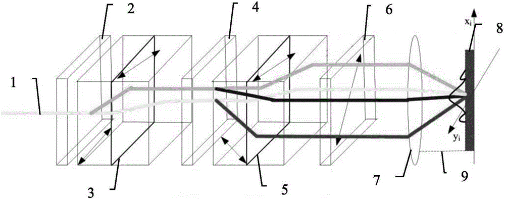
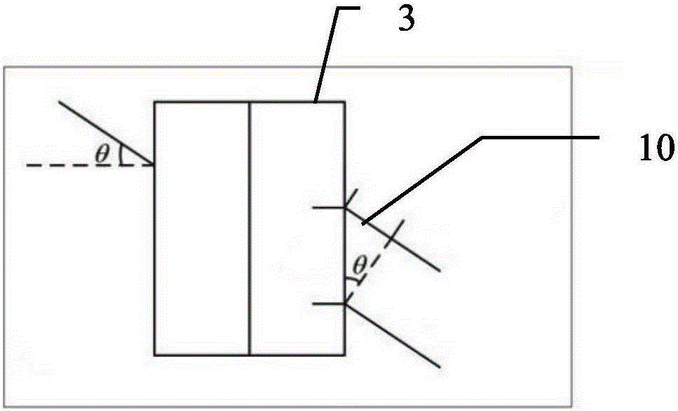
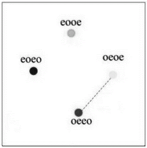
[0048] Select snapshot mode for dynamic targets, a beam of input light emitted by the light source passes through the filter filter placed coaxially along the propagation direction of the incident light, the first improved Sava polarizer MSP1, the half-wave plate HWP, and the second improved The Sava polarizer MSP2 and the analyzer Analyzer are converted into four beams of parallel linearly polarized light eooe, eoeo, oeeo and oeoe, and the four beams of parallel linearly polarized light pass through the coaxial lens Lens and are imaged on the charge-coupled On the CCD element, the first interferogram of the incident light is obtained, and the S of the incident light is obtained after demodulation 0~3 image, where S 1 , S 2 and S 3 The modulation coefficients are equal; wherein, the polarization direction angle of the analyzer is 22.5°, the polarization direction angle of the half-wave plate is 22.5°, θ is the incident angle, and 10 is the optical path difference OPD.

Embodiment 2

[0050] Select both snapshot mode and time-sharing mode for static targets.

[0051] Snapshot mode: a beam of input light emitted by the light source passes through the filter filter, the first improved Sava polarizer MSP1, the half-wave plate HWP, and the second improved Sava polarizer placed coaxially along the propagation direction of the incident light. The mirror MSP2 and the analyzer Analyzer are converted into four parallel beams of linearly polarized light eooe, eoeo, oeeo and oeoe, and the four beams of parallel linearly polarized light are imaged on the charge-coupled device CCD after passing through the coaxially arranged lens Lens, Obtain the first interferogram of the incident light, and obtain the S of the incident light after demodulation 0~3 image, at this time S 1 , S 2 and S 3 The modulation coefficients are equal, wherein, the polarization direction angle of the analyzer is 22.5°, the polarization direction angle of the half-wave plate is 22.5°, θ is the i...

Embodiment 3

[0054] Select both snapshot mode and time-sharing mode for static targets.

[0055] Snapshot mode: a beam of input light emitted by the light source passes through the filter filter, the first improved Sava polarizer MSP1, the half-wave plate HWP, and the second improved Sava polarizer placed coaxially along the propagation direction of the incident light. The mirror MSP2 and the analyzer Analyzer are converted into four parallel beams of linearly polarized light eooe, eoeo, oeeo and oeoe, and the four beams of parallel linearly polarized light are imaged on the charge-coupled device CCD after passing through the coaxially arranged lens Lens, Obtain the first interferogram of the incident light, and obtain the S of the incident light after demodulation 0~3 image, at this time S 1 , S 2 and S 3 The modulation coefficients are equal, wherein, the polarization direction angle of the analyzer is 22.5°, the polarization direction angle of the half-wave plate is 22.5°, θ is the i...


PUM


Abstract

The present invention relates to the field of polarization imaging, and more particularly to a bi-mode full polarization imaging measurement method, comprising the use of a snapshot mode or a time division mode to conduct full polarization imaging measurement to a target. The method is technically performed as follows: an incident light passes sequentially in its transmission direction the coaxially arranged elements of a filter, a first modified Sava-type polarizer, a half-wave plate, a second modified Sava-type polarizer and a polarizer, and is then converted into four parallel beams of linearly polarized light, followed by a process of imaging for a first interference pattern of the incident light which forms S0 ~ 3 images of the incident light after demodulation. Through the 90-degree horizontal rotation of the polarizer along the plane where the polarizer is located and another process of imaging, a second interference pattern of the incident light can be available. The adding of the first interference pattern and the second interference pattern forms a full resolution S0 image that eliminates crosstalk targets. The images S1-S3 are obtained through the demodulation of the differential image of the first interference pattern and the second interference pattern. The polarization direction angle of the polarizer is 22.5 degrees. The present invention provides a bi-mode polarization measurement method for selecting different modes of full polarization imaging for different requirements of different targets.

Description

technical field [0001] The invention relates to the field of polarization imaging, in particular to a dual-mode full polarization imaging deviation measurement method. Background technique [0002] The schematic diagram of the optical path of the snapshot imaging polarization measurement method (SIP) using the traditional Savoyard polarizer combination (CSPs) as the core spectroscopic device is as follows: Figure 1-3 as shown, figure 1 A snapshot imaging polarimeter with a combination of traditional Savoyard polarizers as a transverse shearing beam splitter, including Input light 1 emitted by the light source, Filter 2, the first traditional Savoyard polarizer CSP1 3, half Wave plate HWP 4, polarization direction angle is 22.5°, second traditional Savoyard polarizer CSP2 5, analyzer Analyzer 6, polarization direction angle is 45°, lens Lens 7, charge coupled device CCD 8, lens and charge coupling The spacing f9 between elements, θ is the incident angle, figure 2 It is a...

Claims


Application Information

Patent Timeline
Patent Type & Authority Applications(China)
IPC IPC(8): G01J4/00
Inventor 曹奇志张晶李武钢樊东鑫邓婷戴海青
Owner GUANGXI TEACHERS EDUCATION UNIV
Why Eureka
Try Eureka