Ejector for engine test bed exhaust system

An exhaust system and ejector technology, applied in the field of ejectors, can solve problems such as increased test costs, low ejector ejection performance, and reduced test efficiency

Active Publication Date: 2016-12-07
BEIJING AEROSPACE SANFA HIGH TECH
View PDF7 Cites 11 Cited by
  • Summary
  • Abstract
  • Description
  • Claims
  • Application Information

AI Technical Summary

Problems solved by technology

[0002] When simulating the high-altitude flight state of the engine on the ground, the engine is usually installed in the high-altitude simulation cabin first, and the high-altitude simulation cabin is pumped with air extraction equipment so that the pressure in the high-altitude simulation cabin is the same as the ambient pressure at the altitude of the engine when it is flying at high altitude. In the same way, the engine is ignited and the high-altitude flight simulation test is carried out. During the test, the pressure in the high-altitude simulation cabin must always be kept the same as the ambient pressure at the altitude of the engine when it is flying at high altitude. This requires the exhaust gas from the engine to be discharged to high altitude immediately In the prior art, an ejector is usually used for air extraction, and the ejector uses a relatively high-pressure ejector to eject a low-pressure (or no-pressure) ejected airflow to complete the ejected airflow to suck the ejected airflow. The device for blending injection or delivery, because the ejector has no moving parts, is reliable in use, and is widely used in the exhaust system of the en...

Method used


Image

  • Ejector for engine test bed exhaust system
  • Ejector for engine test bed exhaust system
  • Ejector for engine test bed exhaust system

Examples


Embodiment Construction

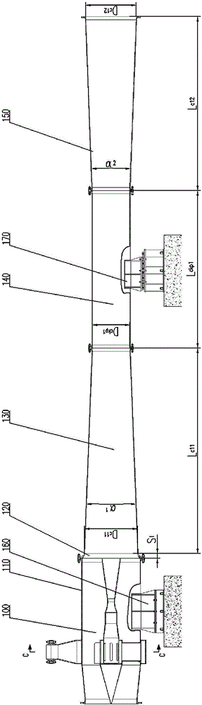
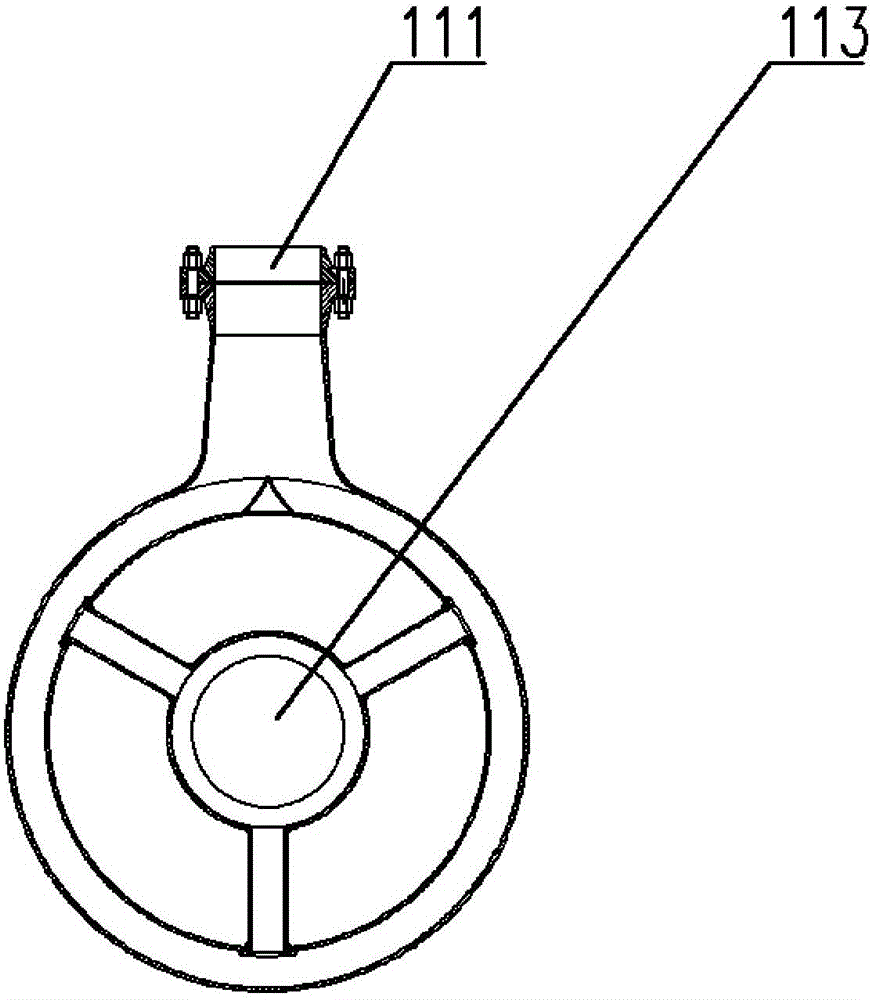
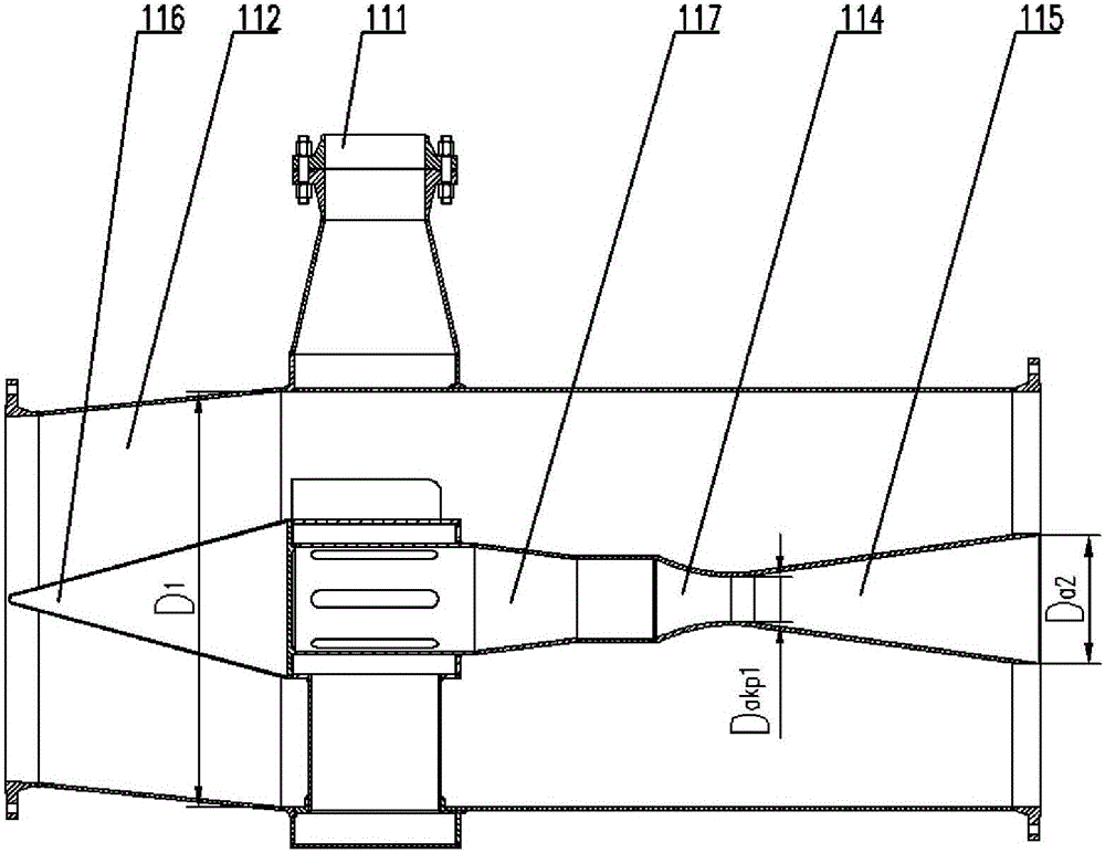
[0044] see Figure 1-6 , an ejector for the exhaust system of an engine test bench, according to the flow direction of the ejected airflow, the ejector 100 includes a low-pressure chamber 110, a transition section 120, and a blending and converging section that are sequentially fixedly connected coaxially 130, blending straight section 140, blending expansion section 150, the low-pressure chamber 110 includes a low-pressure chamber housing 112 and flanges fixedly connected to both ends of the low-pressure chamber housing 112, and the interior of the low-pressure chamber 110 is drawn according to The flow direction of the jet flow is coaxially fixedly connected successively with a circular ring diversion flow guide device 113, a jet flow delivery pipeline 117, a jet flow convergence section 114, a jet flow expansion section 115, and the entrance of the annular split flow guide device 113 It is fixedly connected with the injection air intake manifold 111, and the outlet is fixed...


PUM


Abstract

The invention discloses an ejector for an engine test bed exhaust system. The ejector comprises a low-pressure chamber, a transition section, a mixing convergence section, a mixing equal-straight section and a mixing expansion section, all of which are sequentially and coaxially connected. The low-pressure chamber comprises a low-pressure chamber shell and a flange. An annular flow diverting and guiding device, an ejecting airflow conveying pipeline, an ejecting airflow convergence section and an ejecting airflow expansion section are sequentially and coaxially connected into the low-pressure chamber. An inlet of the annular flow diverting and guiding device is connected with an ejecting airflow intake manifold, the center line of the ejecting airflow conveying pipeline coincides with that of the low-pressure chamber shell, an outlet of the low-pressure chamber and an outlet section of the ejecting airflow expansion section are located on the same vertical plane, the low-pressure chamber is connected with an ejector fixed support, and the mixing equal-straight section is connected with an ejector movable support. The ejector is high in ejection performance, testing efficiency is improved, the testing cost is reduced, and the ejector movable support absorbs the axial length change caused by thermal expansion and cold shrinkage of the ejector in a connected mode.

Description

technical field [0001] The invention relates to an ejector, in particular to an ejector used for the exhaust system of an engine test bench. Background technique [0002] When simulating the high-altitude flight state of the engine on the ground, the engine is usually installed in the high-altitude simulation cabin first, and the high-altitude simulation cabin is pumped with air extraction equipment so that the pressure in the high-altitude simulation cabin is the same as the ambient pressure at the altitude of the engine when it is flying at high altitude. In the same way, the engine is ignited and the high-altitude flight simulation test is carried out. During the test, the pressure in the high-altitude simulation cabin must always be kept the same as the ambient pressure at the altitude of the engine when it is flying at high altitude. This requires the exhaust gas from the engine to be discharged to high altitude immediately In the prior art, an ejector is usually used f...

Claims


Application Information

Patent Timeline
IPC IPC(8): G01M15/02F04F5/16
CPCF04F5/16G01M15/02
Inventor 王文彬赵聚均李强
Owner BEIJING AEROSPACE SANFA HIGH TECH
Why Eureka
Try Eureka