Double-array probe based rail weld ultrasonic-imaging detecting method and system

A double-array and rail technology, which is applied to the analysis of solids using sound waves/ultrasonic waves/infrasonic waves, material analysis using sound waves/ultrasonic waves/infrasonic waves, and measuring devices. and the influence of fatigue degree to achieve the effect of improving detection efficiency and reliability of detection results and reducing labor intensity

Inactive Publication Date: 2016-12-07
GUANGDONG GOWORLD
View PDF7 Cites 11 Cited by
  • Summary
  • Abstract
  • Description
  • Claims
  • Application Information

AI Technical Summary

Problems solved by technology

When using K-type scanning or tandem scanning, due to the use of single-chip probes, in order to scan the entire height of the weld, the two probes must move opposite or opposite at the same speed, so it is difficult to complete by manual operation. Need to be equipped with professional scanning equipment
However, the parts that need to be inspected for rail welds include K-type scanning at the rail head, K-type scanning at the bottom of the rail, and serial scanning at the rail waist. Due to the particularity of the rail structure, it is necessary to ensure that the coupling effect of the probe has an The requirements are very strict, and due to the heavy workload of the inspection, the adjustment and installation of the scanning device is time-consuming and laborious, and the inspector needs to operate the scanning device to move the probe at a constant speed relative to or opposite to each other during work, so the labor intensity of the inspector is high, and the inspection The results are easily affected by the operator's operating experience and fatigue

Method used


Image

  • Double-array probe based rail weld ultrasonic-imaging detecting method and system
  • Double-array probe based rail weld ultrasonic-imaging detecting method and system
  • Double-array probe based rail weld ultrasonic-imaging detecting method and system

Examples


Embodiment Construction

[0038] In order to make the object, technical solution and advantages of the present invention clearer, the present invention will be further described in detail below in conjunction with the accompanying drawings.

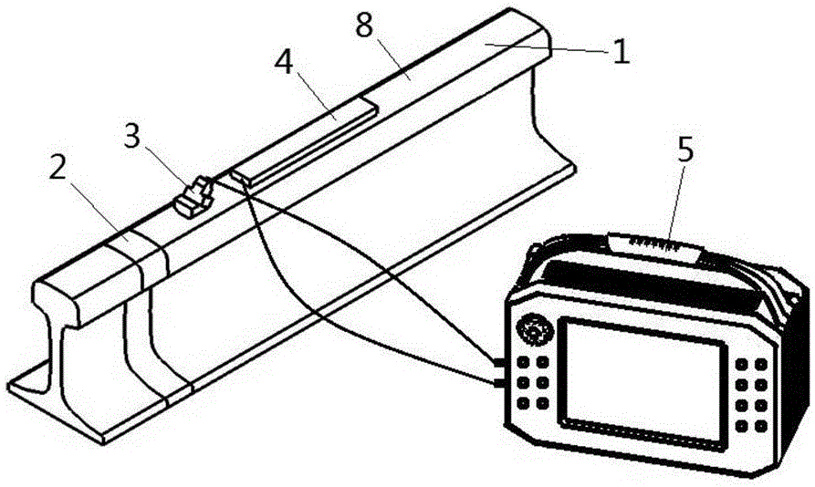
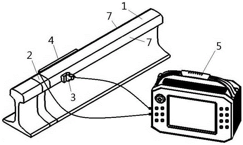
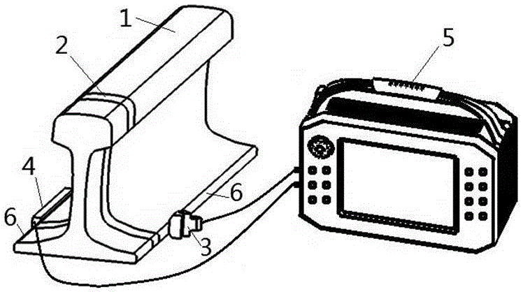
[0039] An ultrasonic imaging detection method for rail welds based on dual-array probes in an embodiment of the present invention, firstly, when performing serial scanning of rail welds, such as figure 1 As shown, two array probes are arranged one behind the other on the rail tread 8 on the side of the weld 2 of the rail 1, the array probe on the near side of the weld is used as the transmitting array probe 3, and the array probe on the far side of the weld is used as The receiving array probe 4, the transmitting array probe and the receiving array probe are attached to the rail tread through the coupling agent; when performing K-type scanning of the rail weld rail head, if figure 2 As shown, an array probe is arranged on the two sides 7 of the rail head on one s...


PUM


Abstract

An embodiment of the invention discloses a double-array probe based rail weld ultrasonic-imaging detecting method. The method includes: arranging an emitting array probe and a receiving array probe on a detected rail; allowing the receiving array probe to be fixedly absorbed on the detected rail and the emitting array probe to be placed on a plurality of fixed position points in back-and-forth motion or in a sequential manner so as to enable ultrasonic wave to cover welds of the detected rail; the receiving array probe receiving ultrasonic echo of the ultrasonic wave emitted through the emitting array probe and reflected through defect surfaces of the welds; calculating height values of the defects by determining start and final positions of echo beams of the ultrasonic wave of weld defect reflection received by array chips on the receiving array probe. The invention further discloses a double-array probe based rail weld ultrasonic-imaging detecting system. By the arrangement, various planar defects existing in the rail welds can be detected rapidly, effectively and comprehensively, and detection efficiency and detection result reliability are effectively improved.

Description

technical field [0001] The invention relates to an ultrasonic nondestructive testing technology, in particular to a method and system for ultrasonic imaging testing of rail welds based on dual array probes. Background technique [0002] For the detection of rail welds, especially planar defects in rail welds, such as light spots, gray spots, cracks, incomplete penetration and fatigue cracks, etc., the existence of these defects not only reduces the effective cross-section of the rail, but also It may also cause stress concentration, which will directly pull the rail weld apart or break the rail, so it is the most dangerous defect. When these planar defects are detected by ultrasonic waves, the reflected waves propagate in other directions according to the law of reflection and cannot return along the incident path. Therefore, it is difficult to detect with a single probe, so dual probes are generally used for detection. The conventional detection method is to use two single...

Claims


Application Information

Patent Timeline
Patent Type & Authority Applications(China)
IPC IPC(8): G01N29/26G01N29/06
CPCG01N29/06G01N29/26G01N29/262
Inventor 付汝龙詹红庆陈伟陈建华
Owner GUANGDONG GOWORLD
Why Eureka
Try Eureka