Material electric field shielding effectiveness testing system and method based on rectangular waveguide

A rectangular waveguide and electric field shielding technology, which is applied in the field of material electric field shielding effectiveness testing systems based on rectangular waveguides, can solve problems such as inability to test shielding effectiveness, and achieve the effect of simple operation

Active Publication Date: 2016-12-07
NORTH CHINA ELECTRIC POWER UNIV (BAODING)
View PDF2 Cites 13 Cited by
  • Summary
  • Abstract
  • Description
  • Claims
  • Application Information

AI Technical Summary

Problems solved by technology

However, this method has the following problems. The polarization direction of the electric field intensity of the TEM mode excited by the coaxial flange is axisymmetric. Therefore, when testing anisotropic materials, the coaxial waveguide TEM mode reflects various polarizations. The "average effect" of the plane wave shielding effectiveness in the same direction cannot test the shielding effectiveness of anisotropic materials under different electric field polarization directions

Method used


Image

  • Material electric field shielding effectiveness testing system and method based on rectangular waveguide
  • Material electric field shielding effectiveness testing system and method based on rectangular waveguide
  • Material electric field shielding effectiveness testing system and method based on rectangular waveguide

Examples


Embodiment 1

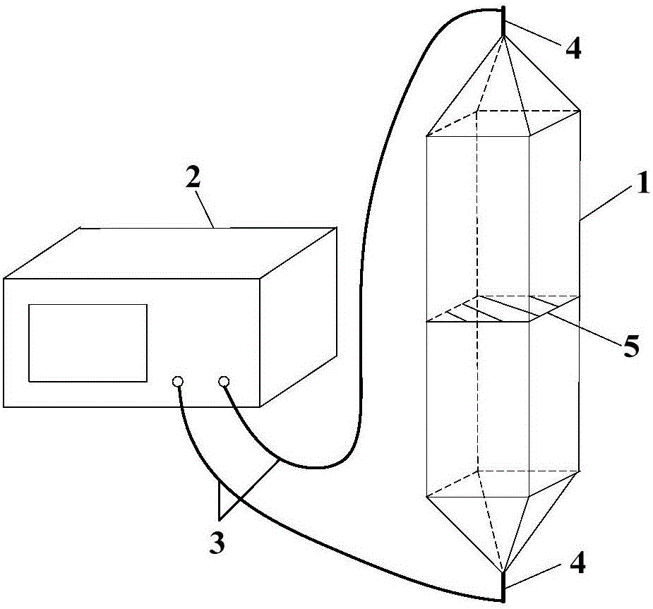
[0035] A material electric field shielding effectiveness test system based on a rectangular waveguide, the system includes: a rectangular waveguide, a network analyzer, a coaxial TEM mode—rectangular TE 10 Mode converters and RF coaxial cables;

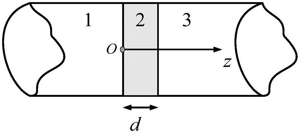
[0036] The rectangular waveguide is a cylindrical shell with a rectangular cross-section made of a metal plate, and the middle of the cylindrical shell is transversely disconnected for placing the material to be tested.

[0037] Coaxial TEM Mode - Rectangular TE 10 There are two mode converters, which are the first coaxial TEM mode—rectangular TE 10 Mode Converter and Second Coaxial TEM Mode - Rectangular TE 10 Mode Converter, First Coaxial TEM Mode - Rectangular TE 10 The first end of the mode converter is connected to the first end of the rectangular waveguide, the second coaxial TEM mode—rectangular TE 10 The first end of the mode converter is connected to the second end of the rectangular waveguide.

[0038] There are two sec...

Embodiment 2

[0041] The method for measuring the effectiveness of electric field shielding using the system in Embodiment 1 includes the following steps:

[0042] Step 1, measure the length and width of the cross-section of the rectangular waveguide, and calculate the TE of the rectangular waveguide 10 Mode cutoff frequency f c1 and the TE of the rectangular waveguide 01 Mode cutoff frequency f c2 , calibrate the network analyzer, adjust the test frequency range of the network analyzer to be f c1 ~ f c2 , connect the test device according to the above requirements.

[0043] Step 2, when the material to be tested is not placed in the rectangular waveguide, operate the network analyzer to measure the parameters

[0044] Step 3, when placing the material to be tested in the rectangular waveguide, operate the network analyzer again to measure the parameters

[0045] The material to be tested is required to satisfy σ / ωε>1000, wherein: σ is the electrical conductivity of the material t...

Embodiment 3

[0109] This embodiment is a preferred implementation of the above two embodiments.

[0110] Take a rectangular waveguide with section length a=10cm, width b=5cm, conductive plate ε c =ε 0 , μ c =μ 0 and d=1 mm. TE can be calculated 10 Mode cut-off frequency f c1 = 1.5GHz, TE 01 Mode cut-off frequency f c2 = 3GHz.

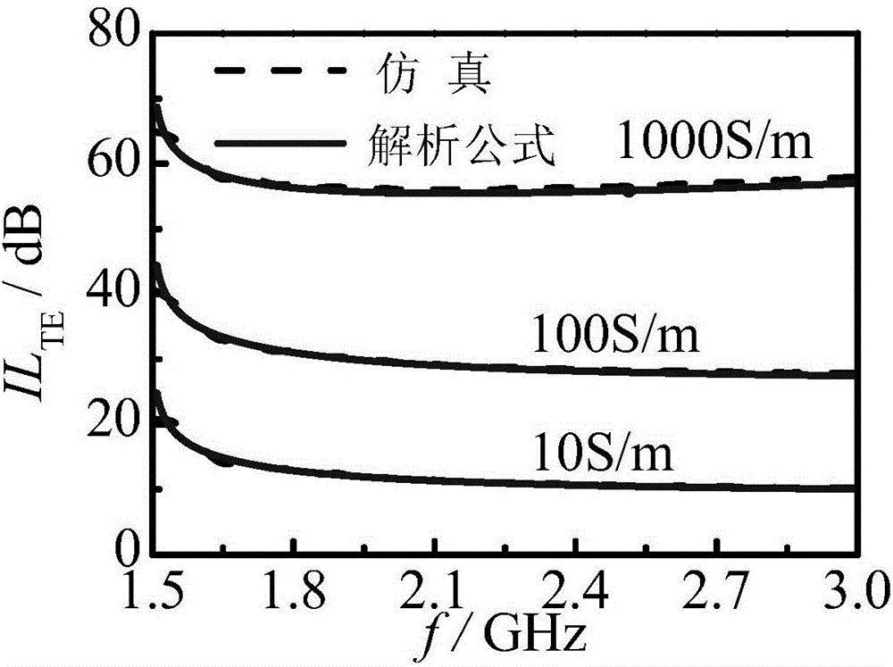
[0111] image 3 When the conductivity of the conductive plate is 10S / m, 100S / m and 1000S / m respectively, the conductive plate to TE 10 Comparing the calculation results of the mode insertion loss analytical formula (solid line, formula (18)) and the full-wave simulation results, it can be seen that the two curves are in good agreement, which verifies the correctness of the analytical formula.


PUM


Abstract

The invention relates to the technical field of electromagnetic shielding, in particular to a material electric field shielding effectiveness testing system and method based on rectangular waveguide. Adopted devices include the rectangular waveguide, a network analyzer, a coaxial TEM mode-rectangular TE10 mode converter and a radio frequency coaxial cable. During testing, a material to be tested is transversely placed at the middle disconnection position of the rectangular waveguide, and the two disconnection ends press the material to be tested; the network analyzer is used for measuring S21 parameters before and after the material to be tested is placed, material electric field shielding efficiency is obtained through formula computing, and the conductivity of the material to be tested is estimated. The method can be used for testing the electric field shielding effectiveness anisotropic materials in different electric field polarization directions, and the defect of a flange coaxial method is made up.

Description

technical field [0001] The invention belongs to the technical field of electromagnetic shielding, and in particular relates to a material electric field shielding effectiveness testing system and method based on a rectangular waveguide. Background technique [0002] Electromagnetic shielding is the main technical measure to suppress electromagnetic disturbance through space field coupling. Traditionally, electromagnetic shielding is implemented by enclosing disturbance sources or sensitive objects with shielding enclosures made of metallic materials. Metal has excellent electrical conductivity, and its shielding effect on electromagnetic waves is high enough. Therefore, the focus of the shielding effectiveness analysis of metal shields is the influence of openings and seams. In recent years, with the development of material science and technology, more and more non-metal plate-type conductive materials have been applied in electromagnetic shielding, such as metal foam, car...

Claims


Application Information

Patent Timeline
Patent Type & Authority Applications(China)
IPC IPC(8): G01R31/00
Inventor 焦重庆李顺杰
Owner NORTH CHINA ELECTRIC POWER UNIV (BAODING)
Why Eureka
Try Eureka