A Method of Image Boundary Element Processing

A processing method and boundary element technology, applied in image data processing, instruments, complex mathematical operations, etc., can solve the problems of inability to use extrapolation, machine time consumption, low precision, etc., to improve R&D efficiency and reduce machine time. Time consumption and the effect of improving accuracy

Active Publication Date: 2019-10-22
苏州中源广科信息科技有限公司
View PDF4 Cites 0 Cited by
  • Summary
  • Abstract
  • Description
  • Claims
  • Application Information

AI Technical Summary

Problems solved by technology

However, when using multi-level boundary element methods, a large amount of auxiliary calculations will be added, and extrapolation cannot be used to improve accuracy
At the same time, the matrix generated by the multi-level boundary element method has a very large condition number, which will cause new problems in matrix inversion
Moreover, in dealing with singularity problems, especially in dealing with the most difficult cracks, etc., the accuracy is not high, and it consumes a lot of machine time

Method used


Image

  • A Method of Image Boundary Element Processing
  • A Method of Image Boundary Element Processing

Examples


Embodiment

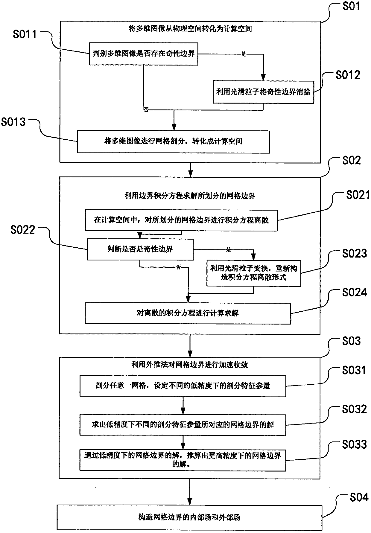
[0034] Example: such as figure 1 As shown, an image boundary element processing method includes the following steps.

[0035] S01: Transform multi-dimensional images from physical space to computational space.

[0036] Specifically, step S01 includes the following steps.

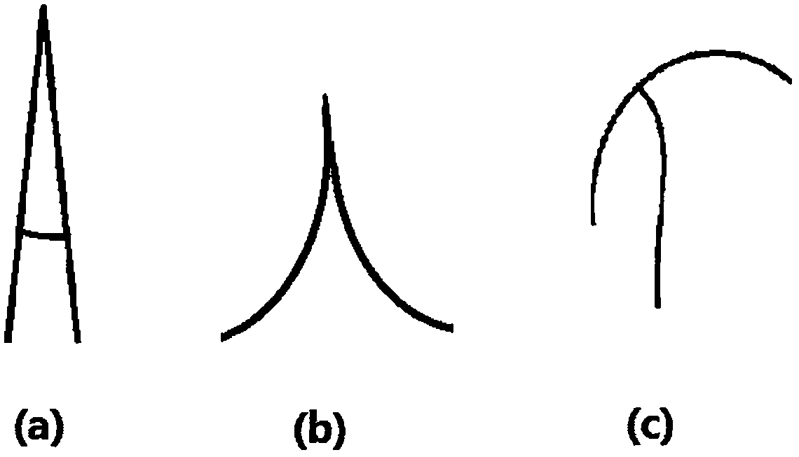
[0037] S011: Determine whether there is a singularity boundary in the multi-dimensional image, if yes, go to step S012; if not, go to step S013.

[0038] S012: Use smooth particles to eliminate the singularity boundary, go to step S013.

[0039] Further, the step S012 includes the following steps.

[0040] S0121: Select a function class that utilizes smooth particle transformation. This type of function satisfies: at the singular point, the function value is 0; near the singular point, the function value tends to 0; and the derivative is not 0.

[0041] Further, in the step S0121, the function class using smooth particle transformation is the sim function class, one of the double power function classes. ...


PUM


Abstract

The invention discloses an image boundary element processing method. The image boundary element processing method comprises the following steps of: S01, converting a multi-dimensional image from a physical space to a computing space, wherein the step S01 comprises the following steps of: S011, judging whether the multi-dimensional image has a singularity boundary or not, if so, entering the step S012, and if not, entering the step S013; S012, eliminating the singularity boundary by utilizing a smoothed particle, and entering the step S013; and S013, performing mesh generation of the multi-dimensional image, and converting into the computing space; S02, solving a divided mesh boundary by utilizing a boundary integral equation; S03, performing accelerated convergence of the mesh boundary by utilizing an extrapolation method; and S04, constructing an internal field and an external field of the mesh boundary. According to the image boundary element processing method disclosed by the invention, the physical space of the image is converted into the computing space by utilizing a smoothed particle method; the converted computing space is suitable for the extrapolation method; therefore, the computing precision is increased; and the mesh processing number is reduced.

Description

technical field [0001] The invention relates to the field of image boundary processing, in particular to an image boundary element processing method. Background technique [0002] The smooth particle method is a Lagrangian mesh-free particle method. It uses the kernel function to approximate the physical problems, and uses discrete particles to describe the macroscopic continuous distribution of microscopic fluids that are still particles, and each particle carries various properties of the fluid at its location, such as mass, density, and velocity. , energy, etc. The smooth particle method was proposed independently by Lucy (1977) and Gingold & Monaghan (1977) to deal with astrophysical problems. Later, the smooth particle method was extended to the fields of aerodynamics, incompressibility, explosion, solid mechanics, and elastic bodies. [0003] Singular boundaries often appear in images. For the processing of singular boundaries, there are currently many traditional m...

Claims


Application Information

Patent Timeline
Patent Type & Authority Patents(China)
IPC IPC(8): G06F17/11G06F17/17G06T17/30
Inventor 张麟
Owner 苏州中源广科信息科技有限公司
Why Eureka
Try Eureka