Smart antenna directional pattern synthesis algorithm for RFID reader based on improved particle swarm

A technology of pattern synthesis and particle swarm improvement, applied in the field of radio frequency communication, can solve the problems of inappropriate RFID reader beam forming, difficult application of smart antennas, etc., and achieve the effect of improving anti-interference performance

Inactive Publication Date: 2016-12-07
TIANJIN POLYTECHNIC UNIV
View PDF2 Cites 6 Cited by
  • Summary
  • Abstract
  • Description
  • Claims
  • Application Information

AI Technical Summary

Problems solved by technology

As the communication environment becomes more and more complex, the classic pattern synthesis techniques such as Dolf-Chebyshev synthesis technology and Taylor synthesis technology can no longer meet the needs of co

Method used


Image

  • Smart antenna directional pattern synthesis algorithm for RFID reader based on improved particle swarm
  • Smart antenna directional pattern synthesis algorithm for RFID reader based on improved particle swarm
  • Smart antenna directional pattern synthesis algorithm for RFID reader based on improved particle swarm

Examples


Example Embodiment

[0038] The main purpose of the present invention is to propose an improved particle swarm-based RFID reader smart antenna pattern synthesis algorithm, which can optimize the excitation amplitude of each antenna element to obtain the target radiation pattern, and improve the anti-interference performance of the antenna array.

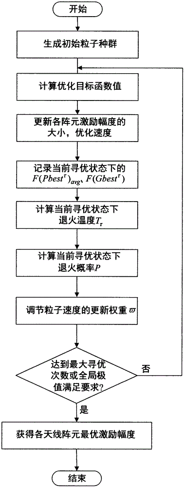
[0039] Such as figure 1 As shown, it specifically includes the following steps:
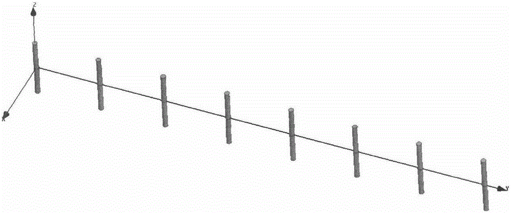
[0040] Step 1: Construct the optimized objective function of the smart antenna. Taking the linear array as an example, for the N-element linear array, the radiation pattern function can be expressed as:

[0041] F ( θ ) = X l = 1 N A t e j i ( 2 π λ d s i n θ - Δφ B ) - - - ( 1 )

[0042] Where: A i Represents the excitation current amplitude of the i-th antenna element, λ represents the wavelength, d represents the distance between each antenna element, θ represents the azimuth angle,...


PUM


Abstract

The invention belongs to the technical field of radio-frequency communication, and relates to a smart antenna directional pattern synthesis algorithm for an RFID reader based on an improved particle swarm. The method comprises the following steps of: analyzing the relationship between a radiation directional pattern and the excitation amplitudes, constructing an optimized objective function of a smart antenna, taking the excitation current amplitudes of array elements as optimization parameters, setting up an optimization particle model by adopting the traditional particle swarm algorithm, and improving the local searching capability and the global searching capability of the optimization particle model by introducing a simulated annealing algorithm, so that the excitation amplitudes of various array elements are determined. By means of the method, the proper array element excitation amplitude can be selected; the radiation directional pattern can be optimized; the null characteristic can be realized; the anti-interference capability of an antenna array in a UHF RFID system can be effectively improved; and the smart antenna directional pattern synthesis algorithm disclosed by the invention has a great practical significance for improving the performance of the RFID system.

Description

technical field [0001] The invention belongs to the technical field of radio frequency communication, and in particular relates to an improved particle swarm-based comprehensive algorithm for the pattern of an RFID reader's smart antenna. Background technique [0002] Radio Frequency Identification (RFID) is a wireless communication technology that realizes data interaction through electromagnetic signals. In recent years, RFID systems have been widely used in various fields such as industrial production, intelligent transportation, and asset management due to their advantages of non-contact, non-line-of-sight, high precision, and low cost. As the key factor to realize wireless data communication in the RFID system, the antenna acts as a bridge between the reader and the tag. Common RFID readers use a single antenna to radiate electromagnetic waves, which has a wide radiation range, a fixed radiation pattern, and low gain, resulting in weak anti-interference ability of the ...

Claims


Application Information

Patent Timeline
IPC IPC(8): G06F17/50G06N3/00
CPCG06F30/20G06N3/006
Inventor 李建雄韩晓迪陈明省宋战伟闫必行
Owner TIANJIN POLYTECHNIC UNIV
Why Eureka
Try Eureka