RFID antenna impedance self-adaptive adjustment method under severe conditions

An adaptive adjustment, antenna impedance technology, applied in the field of wireless communication, can solve the problems of RF front-end impedance mismatch, communication failure, etc., to improve the efficiency of RFID communication and improve the reliability of RFID communication.

Inactive Publication Date: 2016-12-07
HUAZHONG UNIV OF SCI & TECH
View PDF4 Cites 18 Cited by
  • Summary
  • Abstract
  • Description
  • Claims
  • Application Information

AI Technical Summary

Problems solved by technology

In the low-frequency RFID system, the reader and the tag transmit energy and data through electromagnetic induction. The low-frequency RFID technology has the advantages of wireless identification, waterproof, antimagnetic, high temperature resistance, long service life, free label information change, and low cost. Oil exploration, access management, tool identification, electronic locking anti-theft and other fields are widely used, which greatly improves the reliability and efficiency of work. However, RFID is used as electromagnetic field communication, and its working environment will have a certain impact on RFID communication, especially in oil wells. Under harsh working conditions such as metal pipelines, saturated salt water, mud, and high temperature during mining, the impedance of the RFID antenna will change, resulting in a mismatch in the impedance of the RF front-end, which will have a greater impact on RFID communication. In most cases, it will cause communication failure, so it is complex and changeable The environment and harsh working conditions pose challenges to the robustness and environmental insensitivity of RFID communication

Method used


Image

  • RFID antenna impedance self-adaptive adjustment method under severe conditions
  • RFID antenna impedance self-adaptive adjustment method under severe conditions
  • RFID antenna impedance self-adaptive adjustment method under severe conditions

Examples


Embodiment Construction

[0037] In order to make the object, technical solution and advantages of the present invention clearer, the present invention will be further described in detail below in conjunction with the accompanying drawings and embodiments. It should be understood that the specific embodiments described here are only used to explain the present invention, not to limit the present invention. In addition, the technical features involved in the various embodiments of the present invention described below can be combined with each other as long as they do not constitute a conflict with each other.

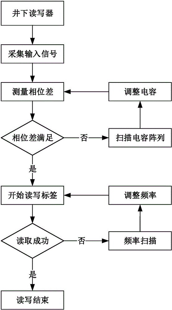
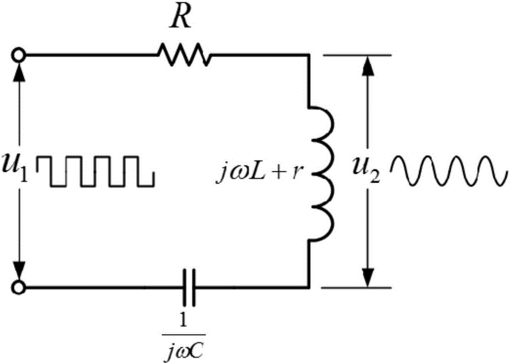
[0038] figure 1 It is the overall method flow of the present invention. Before introducing this method, first briefly introduce the working principle of RFID, the impact of harsh working conditions on the RF front-end of the reader, and the series RLC resonant circuit.

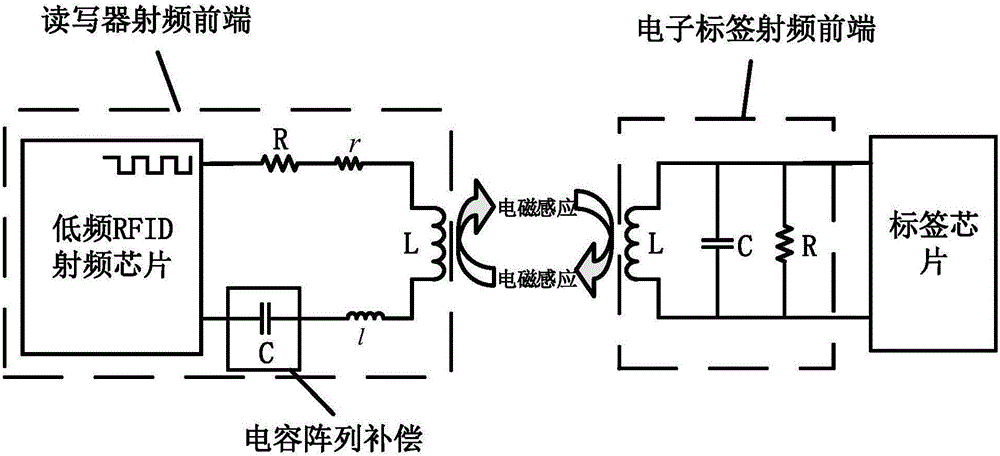
[0039] see figure 2 , The working principle of RFID is to realize the exchange and transmission of data and energy through...


PUM


Abstract

The invention discloses an RFID antenna impedance self-adaptive adjustment method under the severe conditions. The implementation of the method mainly comprises the following steps of input signal acquisition, phase difference measurement, phase difference judgment, capacitance compensation, read-write tag judgment and frequency compensation. RFID radio frequency chip and antenna side signals are mainly acquired in the input signal acquisition. Phase difference measurement and judgment are performed on the acquired signals. The capacitance meeting the requirement of phase difference is selected by the capacitance compensation so that radio frequency front-end antenna impedance matching can be realized. When tag reading and writing still fail under the condition that the phase difference meets the requirement, radio frequency front-end antenna impedance matching is realized by changing radio frequency chip transmitting frequency through the frequency compensation. The influence of high temperature, high pressure, mud media, metal environment and other severe conditions on RFID antenna impedance in low-frequency RFID communication can be mainly solved so that the method has important meaning in enhancing the reliability of RFID communication and then enhancing the efficiency of RFID communication.

Description

technical field [0001] The invention belongs to the technical field of wireless communication, and in particular relates to a method for adaptively adjusting the impedance of an RFID antenna under severe working conditions. Background technique [0002] RFID (Radio Frequency Identification, Radio Frequency Identification) is a method of identifying targets and reading relevant data through radio signals. A general RFID system includes an RFID tag and a reader, wherein the RFID tag acts as the command carrier, and the reader acts as the command reader. In the low-frequency RFID system, the reader and the tag transmit energy and data through electromagnetic induction. The low-frequency RFID technology has the advantages of wireless identification, waterproof, antimagnetic, high temperature resistance, long service life, free label information change, and low cost. Oil exploration, access management, tool identification, electronic locking anti-theft and other fields are widel...

Claims


Application Information

Patent Timeline
Patent Type & Authority Applications(China)
IPC IPC(8): G06K19/077
CPCG06K19/07771G06K19/07773
Inventor 陶波艾其江朱继轩孙虎龚元尹周平
Owner HUAZHONG UNIV OF SCI & TECH
Why Eureka
Try Eureka