
Machine vision-based unmanned aerial vehicle automatic detection method and unmanned aerial vehicle control method

An automatic detection and machine vision technology, applied in aircraft traffic control, multi-machine traffic management, instruments, etc., can solve the problems of expensive radar, high detection cost, and poor anti-interference, so as to improve detection accuracy and reduce detection cost , the effect of improving the accuracy

Inactive Publication Date: 2016-12-07
HUAZHONG UNIV OF SCI & TECH
View PDF12 Cites 26 Cited by
  • Summary
  • Abstract
  • Description
  • Claims
  • Application Information

AI Technical Summary

Problems solved by technology

[0003] The existing radar-based UAV air defense detection system has poor anti-interference ability; and for the vast sky, the UAV is small in size, has low contrast with the sky background, and the background is complex and changeable. The human-machine detection system is prone to generate a large number of false alarms during the detection process, and the detection accuracy is low; and the radar is expensive, and the detection cost is extremely high

Method used


Image

  • Machine vision-based unmanned aerial vehicle automatic detection method and unmanned aerial vehicle control method
  • Machine vision-based unmanned aerial vehicle automatic detection method and unmanned aerial vehicle control method
  • Machine vision-based unmanned aerial vehicle automatic detection method and unmanned aerial vehicle control method

Examples


Embodiment Construction

[0074] In order to make the object, technical solution and advantages of the present invention clearer, the present invention will be further described in detail below in conjunction with the accompanying drawings and embodiments. It should be understood that the specific embodiments described here are only used to explain the present invention, not to limit the present invention. In addition, the technical features involved in the various embodiments of the present invention described below can be combined with each other as long as they do not constitute conflicts with each other.

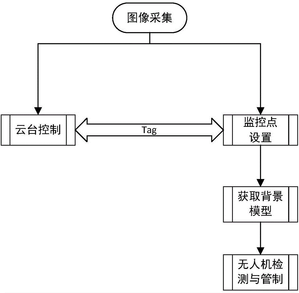
[0075] Such as figure 1 As shown, it is a schematic diagram of the machine vision-based automatic detection method for unmanned aerial vehicles and the control method for unmanned aerial vehicles provided by the embodiment of the present invention, including image acquisition, PTZ control, monitoring point setting, background model establishment, and unmanned aerial vehicle detection and control ...


PUM


Abstract

The invention discloses a machine vision-based unmanned aerial vehicle automatic detection method and an unmanned aerial vehicle control method. According to the machine vision-based unmanned aerial vehicle automatic detection method and the unmanned aerial vehicle control method, an image acquisition device is utilized to automatically inspect the sky; adaption to the change of illumination is realized, and the direct irradiation of strong light is avoided; an image sequence of an area to be detected is obtained; a low-altitude aircraft such as an unmanned aerial vehicle is detected automatically according to target motion characteristics of images in the sequence and the difference of a target and background in each image; and the satellite positioning channel and remote control channel of the unmanned aerial vehicle are subjected to radio interference, so that control on the unmanned aerial vehicle can be realized. With the method of the invention adopted, a whole space domain can be monitored; the orientation of an optical imaging sensor can be automatically adjusted, so that the optical imaging sensor will not be exposed to the direct irradiation of strong light; and environmental background can be automatically learned in real time; and a target can be detected and captured. The method has strong adaptability to the environment and has outstanding economic and practical values.

Description

technical field [0001] The invention belongs to the technical field of image processing and pattern recognition, and more specifically, relates to a machine vision-based automatic detection method for unmanned aerial vehicles and a control method for unmanned aerial vehicles. Background technique [0002] UAV technology is becoming more and more mature, and there are no perfect laws and regulations for the time being, leading to the prevalence of "black flying". UAVs can flexibly reach areas that humans cannot reach, obtain confidential information, and endanger public safety. [0003] The existing radar-based UAV air defense detection system has poor anti-interference ability; and for the vast sky, the UAV is small in size, has low contrast with the sky background, and the background is complex and changeable. The human-machine detection system is prone to generate a large number of false alarms during the detection process, and the detection accuracy is low; and the radar...

Claims


Application Information

Patent Timeline
IPC IPC(8): G08G5/00G06K9/38G06K9/00
CPCG08G5/0043G08G5/0069G06V10/28G06F2218/00
Inventor 马杰刘阳
Owner HUAZHONG UNIV OF SCI & TECH
Learn More