Pressing ring apparatus and reaction chamber

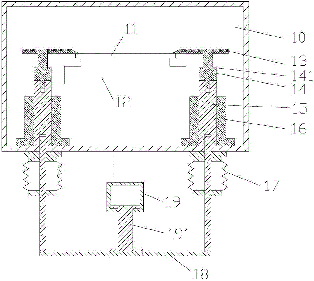
A reaction chamber and pressure ring technology, which is applied in the direction of electrical components, semiconductor/solid-state device manufacturing, circuits, etc., can solve the problems of melting of the support 14, deflection of the pressure ring 13, and affecting the normal lifting of the pressure ring 13, so as to avoid Damage the chip, ensure normal operation, and ensure the effect of normal lifting

Active Publication Date: 2016-12-07
BEIJING NAURA MICROELECTRONICS EQUIP CO LTD
View PDF6 Cites 5 Cited by
  • Summary
  • Abstract
  • Description
  • Claims
  • Application Information

AI Technical Summary

Problems solved by technology

However, there will be such a problem: in a long-term process environment, the support member 14 of the resin material will melt due to high temperature or corrosion, and in severe cases, the pressure ring 13 will be deflected, thereby affecting the normal lifting of the pressure ring 13

Method used


Image

  • Pressing ring apparatus and reaction chamber
  • Pressing ring apparatus and reaction chamber
  • Pressing ring apparatus and reaction chamber

Examples


Embodiment Construction

[0030] In order to enable those skilled in the art to better understand the technical solution of the present invention, the ring pressure device and the reaction chamber provided by the present invention will be described in detail below with reference to the accompanying drawings.

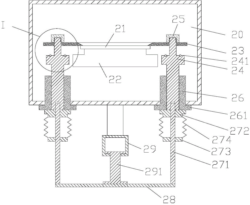
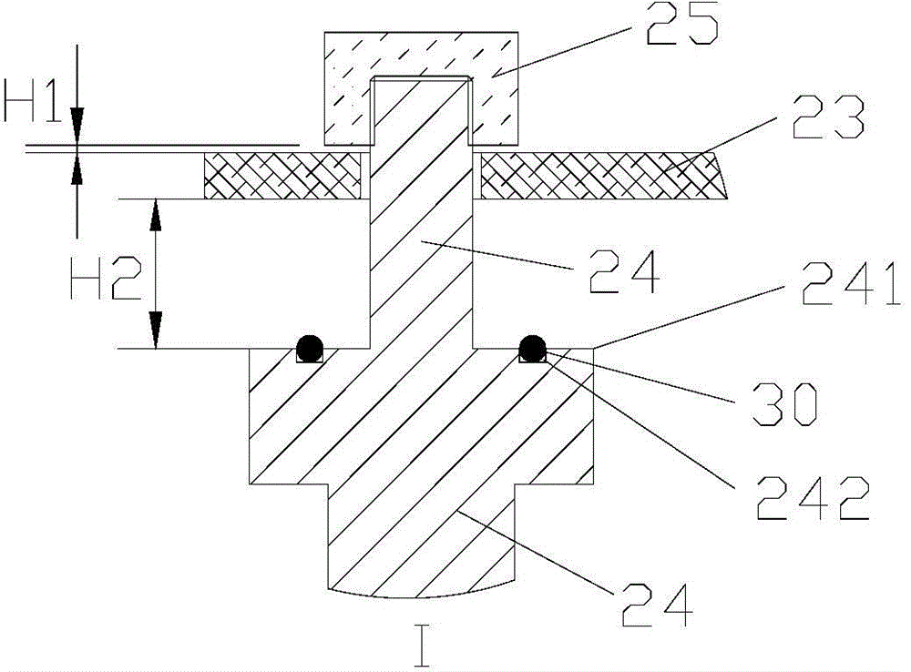
[0031] Figure 2A A cross-sectional view of the pressure ring device provided by the embodiment of the present invention during the process. Figure 2B for Figure 2A Zoom-in view of the middle I region. image 3 A cross-sectional view of the pressing ring device provided by the embodiment of the present invention when performing the operation of picking and placing the sheet. Please also refer to Figure 2A , Figure 2B and image 3 , a chuck 22 is provided in the reaction chamber 20, and the chuck 22 is a device for carrying the wafer 21, and may be an electrostatic chuck, a mechanical chuck, or the like. The pressure ring device is used to cover the edge of the wafer 21 placed on the chu...


PUM


Abstract

The invention provides a pressing ring apparatus and a reaction chamber. The pressing ring apparatus comprises pressing rings and supporting parts which are used for driving the corresponding pressing rings to move up and down; each supporting part comprises a stage surface; the stage surface is provided with a pin column; first through holes are formed in positions, corresponding to the pin columns, on the pressing rings correspondingly; the pin columns pass through the first through holes which are corresponding to the pin columns and are higher than the upper surfaces of the corresponding pressing rings; a blocking part is positioned in a position, which is higher than the upper surface of the corresponding pressing ring, on each pin column; and when the supporting parts jack up the corresponding pressing rings, a preset distance H is formed between the upper surface of the corresponding pressing ring and the lower surface of the corresponding blocking part. By adoption of the pressing ring apparatus provided by the invention, the inclination of the pressing rings or a condition that the pressing rings are separated from the supporting parts can be avoided, so that it is ensured that the pressing rings can accurately press the edge of a wafer; therefore, damage to the wafer can be further avoided; and the normal operation of wafer taking and wafer placement can be ensured.

Description

technical field [0001] The invention relates to the field of semiconductor manufacturing, in particular to a pressure ring device and a reaction chamber. Background technique [0002] In the field of deep silicon etching, etching machines are indispensable equipment in the production process. The quality of the corrosion results is mainly determined by the performance of the equipment process module itself. Therefore, it is necessary to continuously optimize the key technologies that affect the corrosion results. [0003] At present, due to the limitation of the glue-spinning equipment, the edge area close to the edge of the wafer 2-3mm generally cannot be coated with photoresist (used as a mask for etching patterns), resulting in the edge area of ​​the wafer being corroded during the wafer etching process , thereby causing the edge of the wafer to become thinner, and the edge of the wafer is easily broken after being thinned, causing damage and contamination of the wafer, ...

Claims


Application Information

Patent Timeline
Patent Type & Authority Applications(China)
IPC IPC(8): H01L21/687H01L21/67H01L21/683H01L21/68
Inventor 张新云
Owner BEIJING NAURA MICROELECTRONICS EQUIP CO LTD
Why Eureka
Try Eureka