Three-terminal vertical constant-current device with protection function and manufacturing method of three-terminal vertical constant-current device

A protection function and constant current device technology, which is applied in semiconductor/solid state device manufacturing, electrical solid state devices, semiconductor devices, etc., can solve the problems of easy burning, low constant current, and low breakdown voltage, so as to save process cost and reduce area, the effect of enhancing reliability

Inactive Publication Date: 2016-12-07
UNIV OF ELECTRONIC SCI & TECH OF CHINA
View PDF4 Cites 0 Cited by
  • Summary
  • Abstract
  • Description
  • Claims
  • Application Information

AI Technical Summary

Problems solved by technology

However, the current high breakdown voltage of constant current diodes is generally 30-100V, so there is a problem of low breakdown voltage, and the constant current that can be provided is also low, and most constant current diodes cannot cope with the harsh external environment. , in the case of lightning strikes or large voltage and high current generated by grid fluctuations, it is easy to burn out, making it difficult to guarantee the safety of the subsequent drive circuit. A transient voltage suppressor diode (TVS, Transient VoltageSuppressor) is integrated around the constant current diode Finally, the anti-surge capability of the constant current diode and the entire drive system can be enhanced, and the reliability is greatly improved

Method used


Image

  • Three-terminal vertical constant-current device with protection function and manufacturing method of three-terminal vertical constant-current device
  • Three-terminal vertical constant-current device with protection function and manufacturing method of three-terminal vertical constant-current device
  • Three-terminal vertical constant-current device with protection function and manufacturing method of three-terminal vertical constant-current device

Examples


Embodiment Construction

[0053] The following describes the implementation of the present invention through specific specific examples. Those skilled in the art can easily understand other advantages and effects of the present invention from the content disclosed in this specification. The present invention can also be implemented or applied through other different specific embodiments, and various details in this specification can also be modified or changed based on different viewpoints and applications without departing from the spirit of the present invention.

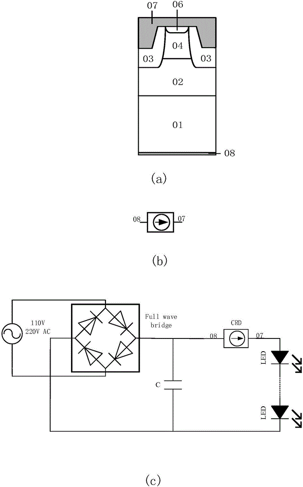
[0054] figure 1 It is a traditional vertical constant current diode, figure 1 There are 3 sub-figures (a), (b), and (c) which represent the device structure diagram, device symbol, and LED drive circuit for traditional vertical constant current diodes.

[0055] Such as figure 1 As shown in (a), the traditional vertical constant current diode device structure includes a heavily doped N-type substrate 01, a first lightly doped N-type epitaxial lay...


PUM


Abstract

The invention provides a three-terminal vertical constant-current device with a protection function and a manufacturing method of the three-terminal vertical constant-current device. The device comprises a vertical constant-current diode and a transient voltage suppresser diode, wherein the vertical constant-current diode comprises a metal anode, an N-type substrate, a first lightly doped N-type epitaxial layer, a first P-type region, a second heavily doped N-type epitaxial layer, a first N-type heavily doped region and a first metal cathode; and the transient voltage suppresser diode comprises another metal anode, another N-type substrate, another first lightly doped N-type epitaxial layer, another heavily doped N-type epitaxial layer, a second P-type region, an oxide layer and a second metal cathode. The transient voltage suppresser diode and the vertical constant-current diode are integrated together, so that the constant-current diode has surge handling capability; the reliability of the constant-current diode and a system is strengthened; and proper breakdown voltage, clamp voltage and peak pulse current of the transient voltage suppresser diode can be obtained through adjusting the junction depth and the concentration of the second P-type region.

Description

Technical field [0001] The invention belongs to the technical field of semiconductor power devices, and in particular relates to a vertical constant current device with a protective function at three ends and a manufacturing method thereof. Background technique [0002] Constant current source is a commonly used electronic equipment and device, which is widely used in electronic circuits. The constant current source is used to protect the entire circuit, even if the voltage is unstable or the load resistance changes greatly, it can ensure the stability of the power supply current. However, the current high breakdown voltage of constant current diodes is generally 30 ~ 100V, so there is a problem of low breakdown voltage, while the constant current that can be provided is also low, and most constant current diodes cannot cope with the harsh external environment , In the case of lightning strikes, large voltages or large currents generated by grid fluctuations, it is easy to burn ...

Claims


Application Information

Patent Timeline
IPC IPC(8): H01L27/08H01L29/861H01L21/822
CPCH01L27/0814H01L21/822H01L29/861
Inventor 乔明李成州卢璐于亮亮何逸涛张波
Owner UNIV OF ELECTRONIC SCI & TECH OF CHINA
Why Eureka
Try Eureka