Stacked power battery pack box body

A power battery pack, layered technology, applied in battery pack components, isolation of batteries from their environment, circuits, etc., can solve problems such as poor sealing performance, large space occupation, and de-soldering at welding places, ensuring verticality and saving energy. Space, easy to stabilize the effect

Active Publication Date: 2016-12-07
BEIJING PRIDE NEW ENERGY BATTERY
View PDF5 Cites 2 Cited by
  • Summary
  • Abstract
  • Description
  • Claims
  • Application Information

AI Technical Summary

Problems solved by technology

The battery pack is generally composed of a box and batteries inside the box. In order to ensure the safety of the internal batteries and electrical components, the box must be waterproof. In the existing power battery box, the same board is generally used. After cutting according to the unfolded drawing, it is then bent and welded. After the welds of the four corners of the box are welded, in order to ensure a beautiful appearance, the external welds must be polished, and often after grinding. Due to trachoma, there is a problem of water leakage in the box body. At the same time, the deformation of the flange edge of the existing box body is relatively large after welding, resulting in poor sealing performance; Strong vibration is generated, and the existing power battery pack box is also poor in anti-seismic effect, often due to vibration, the welding part is desoldered or cracked and water leaks
In addition, the existing power battery pack boxes are generally single-layer boxes. If multi-layer arrangements are to be made, multi-layer brackets must be used, and a box is placed on each layer of brackets, which will inevitably occupy a large space

Method used


Image

  • Stacked power battery pack box body
  • Stacked power battery pack box body
  • Stacked power battery pack box body

Examples


Embodiment Construction

[0035] The principles and features of the present invention are described below in conjunction with the accompanying drawings, and the examples given are only used to explain the present invention, and are not intended to limit the scope of the present invention.

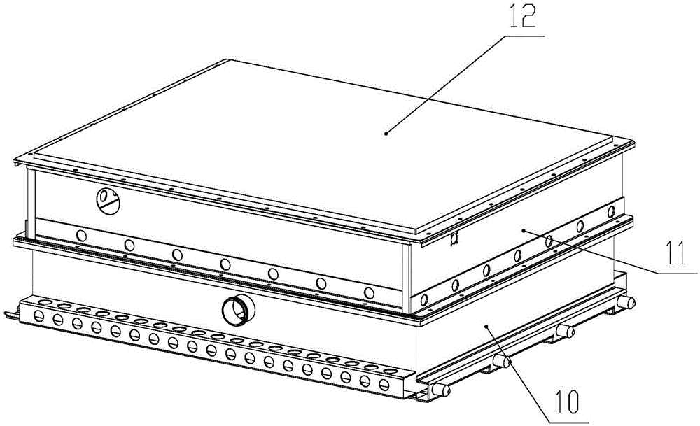
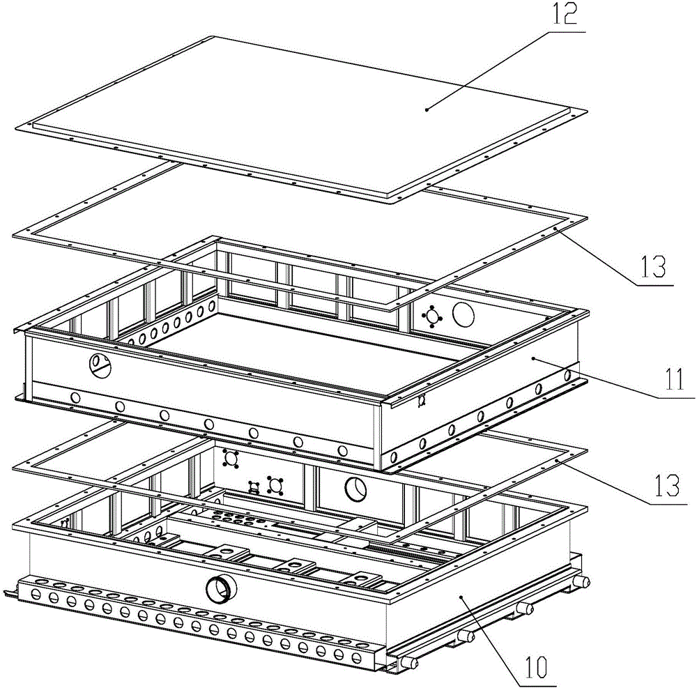
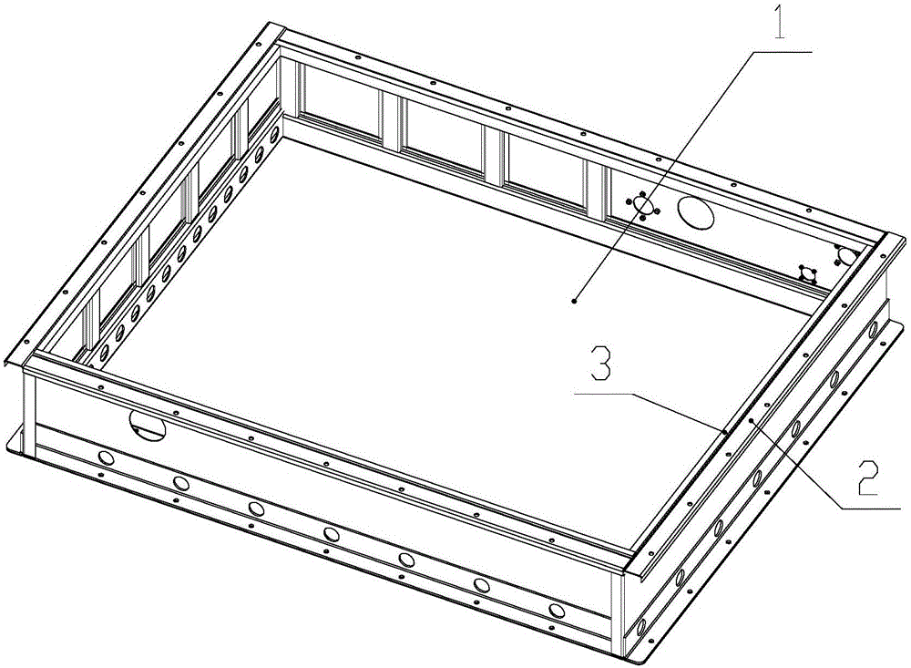
[0036] Such as Figure 1 to Figure 6 as shown, figure 1 It is a schematic three-dimensional structure diagram of a specific embodiment of a laminated power battery pack provided by the present invention; figure 2 for figure 1 The disassembled structural schematic diagram of the specific embodiment shown; image 3 It is a schematic diagram of a three-dimensional structure of a specific embodiment of the upper box; Figure 4 for image 3 The schematic diagram of hiding the stiffener plate in the upper box as shown; Figure 5 for image 3 A schematic diagram of the disassembled structure of the upper box as shown; Figure 6 It is a structural schematic diagram of a specific embodiment of the side plate.

[003...


PUM

PropertyMeasurementUnit
thicknessaaaaaaaaaa

Abstract

The invention relates to a stacked power battery pack box body. The box body comprises a lower-layer box body located on the bottommost layer and an upper-layer box body located on two or more layers, wherein the box bodies of all the layers are connected through flanges; the upper-layer box body comprises a bottom box, four side plates and four locating pipes; the bottom box adopts a cuboid box body structure with an upper open end and consists of a bottom plate and four fences vertically connected on the edges of the bottom plate; the four side plates are same in height; flange sides extending outwards are arranged at the top and bottom of each side plate; the four side plates are fixedly connected to the outer sides of the fences respectively; the lower surfaces of the side plates are flush with the lower surface of the bottom box; the four locating pipes are transversely fixed on the inner sides of the four side plates respectively; the upper surfaces of the four locating pipes are flush; and the upper surfaces of the four locating pipes are higher than the upper surfaces of the side plates. The box body is no need of a bracket due to multilayer direct installation and arrangement, and is reasonable in structure, higher in strength and better in seal property.

Description

technical field [0001] The invention relates to the field of power batteries of electric vehicles, in particular to a laminated power battery pack box. Background technique [0002] In the field of electric vehicles, the power battery pack plays an irreplaceable and important role as the power source of electric vehicles. The battery pack is generally composed of a box and batteries inside the box. In order to ensure the safety of the internal batteries and electrical components, the box must be waterproof. In the existing power battery box, the same board is generally used. After cutting according to the unfolded drawing, it is then bent and welded. After the welds of the four corners of the box are welded, in order to ensure a beautiful appearance, the external welds must be polished, and often after grinding. Due to trachoma, there is a problem of water leakage in the box body. At the same time, the deformation of the flange edge of the existing box body is relatively la...

Claims


Application Information

Patent Timeline
Patent Type & Authority Applications(China)
IPC IPC(8): H01M2/10H01M50/249
CPCH01M50/24H01M50/20Y02E60/10
Inventor 李鸿键王小龙盛力赵孟蔡玉涛杨槐
Owner BEIJING PRIDE NEW ENERGY BATTERY
Why Eureka
Try Eureka