Multisystem integrated antenna

A multi-system, integrated technology, applied in the directions of antennas, antenna arrays, and antenna components, can solve the problems of the limitation of the number of high-frequency antenna elements and low-frequency antenna elements, and the limitation of antenna gain, so as to improve the gain, easy to use, etc. The effect of obtaining and rational use of space

Active Publication Date: 2016-12-07
COMBA TELECOM TECH (GUANGZHOU) CO LTD
View PDF8 Cites 13 Cited by
  • Summary
  • Abstract
  • Description
  • Claims
  • Application Information

AI Technical Summary

Problems solved by technology

[0004] However, due to indicators such as balanced gain and upper sidelobe suppression after electrical downtilt, the selection range of the spacing of the low-frequency radiation array is generally 250mm to 300mm, and the selection range of the spacing of the high-frequency radiation array is generally 105mm to 115mm, and the length of the radome The size is generally limited to less than 2m, so the number of high-frequency antenna elements and low-frequency antenna elements are limited
When the number of elements of the array antenna is limited, the antenna gain corresponding to the array antenna will also be limited, so that it is impossible to realize a high-gain multi-system antenna in a radome

Method used


Image

  • Multisystem integrated antenna
  • Multisystem integrated antenna
  • Multisystem integrated antenna

Examples


Embodiment 1

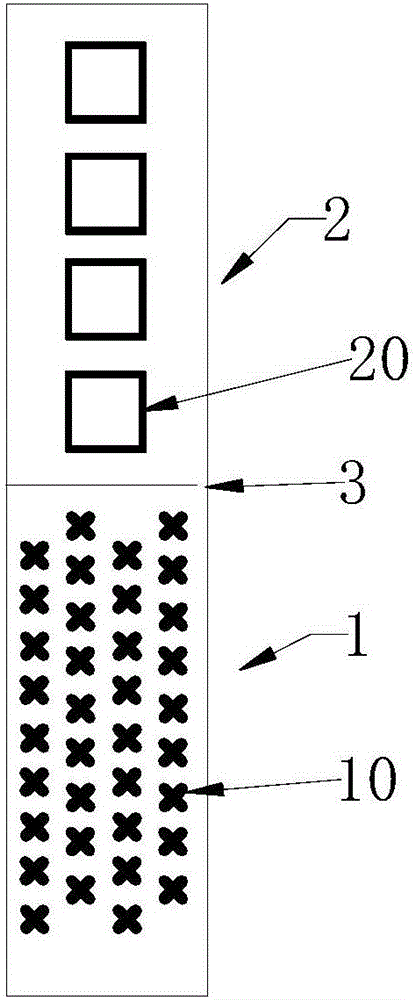
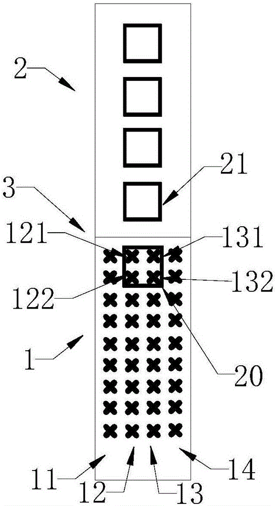
[0040] Such as figure 2 As shown, this embodiment provides a multisystem antenna, including a reflector 3 , and a smart antenna array 1 and a base station antenna array 2 both installed on the reflector 3 . Among them, the smart antenna array 1 and the base station antenna array 2 respectively compose the smart antenna and the base station antenna, so that the antennas of different systems (TD-LTE system and traditional cellular mobile system, such as GSM900MHz and CDMA800MHz) working in different frequency bands share the reflector And the radome, realize the multi-system integration design, which is conducive to the miniaturization of the antenna and saves the installation space.

[0041] The reflector 3 is used as a common reflector of the smart antenna array 1 and the base station antenna array 2, and the smart antenna array 1 and the base station antenna array 2 are electrically connected to the reflector 3, preferably conductively or capacitively coupled.

[0042] The ...

Embodiment 2

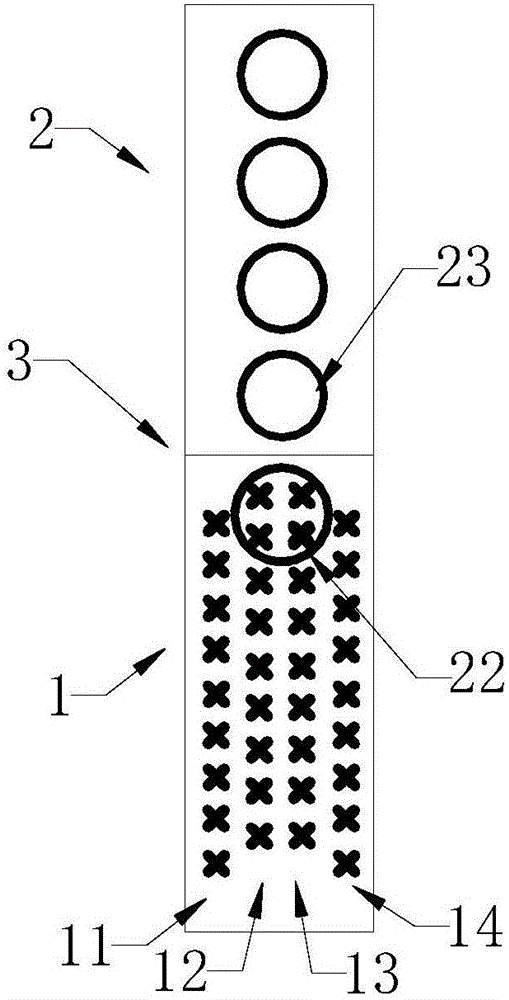
[0054] Such as image 3 As shown, this embodiment provides a multi-system antenna, the main feature of which is that: the radiation structure of the second base station antenna element 22 and the first base station antenna element 23 adopts a ring form. All the other are the same as embodiment one.

Embodiment 3

[0056] Such as Figure 4 As shown, the present embodiment provides a multi-system antenna, the main feature of which is that the base station antenna adopts the form of a multi-frequency shared antenna, that is, the base station antenna array 2 also includes the first base station antenna array element 21 (low frequency The base station antenna array element) is arranged on a plurality of high-frequency base station antenna array elements 200 at the same end of the reflector 3, and the high-frequency base station antenna array element 200 is arranged on the left side of the first base station antenna array element 21. Wherein, the first base station antenna element 21 and the second base station antenna element 20 work at 880-960 MHz, and the high-frequency base station antenna element 200 works at 1710-1880 MHz, and the two form a dual-frequency shared antenna. The smart antenna array works at 1880-1920MHz, 2010-2025MHz, and 2575-2635MHz. All the other are the same as embodi...


PUM


Abstract

The invention provides a multisystem integrated antenna, which comprises a reflector plate, an smart antenna array and a base station antenna array, wherein the smart antenna array and the base station antenna array are arranged on the reflector plate; the smart antenna array is located at the lower end of the reflector plate and comprises a plurality of smart antenna sub-arrays; each smart antenna sub-array comprises a plurality of smart antenna array elements; the base station antenna array comprises a plurality of first base station antenna array elements and a second base station antenna array element; the plurality of first base station antenna array elements are located at the upper end of the reflector plate; and the second base station antenna array element is embedded into gaps of a plurality of smart antenna array elements and surround the plurality of smart antenna array elements of two adjacent intelligent antenna sub-arrays. The plurality of smart antenna array elements are surrounded through at least one second base station antenna array element; and the gaps of the smart antenna arrays are fully utilized; and the number of the base station antenna array elements is increase under the condition of not increasing the size of the reflector plate, so that the target of improving the antenna gain is achieved, and miniaturization of the antenna is facilitated.

Description

technical field [0001] The present invention relates to the communication field, in particular to a multi-system community antenna. Background technique [0002] With the increase of mobile communication network standards and the coexistence of multiple communication systems, in order to optimize resource allocation, save site and antenna resources, reduce the difficulty of property coordination, and reduce investment costs, co-site and co-location system antennas have gradually become an operational The first choice for commercial construction network. [0003] At present, the multi-system antennas selected by operators usually combine smart antenna systems (1880~1920MHz, 2010~2025MHz, 2575~2635MHz) and base station antenna systems (880~960MHz, 1710~1880MHz) in a radome. integrated. Commonly used antenna integration methods such as the design scheme provided by the patent CN 101465473 B (such as figure 1 As shown), the scheme installs the smart antenna array 1 and the ba...

Claims


Application Information

Patent Timeline
Patent Type & Authority Applications(China)
IPC IPC(8): H01Q21/00H01Q21/30H01Q19/10
CPCH01Q21/061H01Q15/14H01Q5/42H01Q1/246
Inventor 孙善球王强李明超黄立文姜维维
Owner COMBA TELECOM TECH (GUANGZHOU) CO LTD
Why Eureka
Try Eureka