Photocatalysis miniature liquid-solid fluidized bed reactor
A fluidized bed reactor and photocatalysis technology, applied in the field of photocatalysis, can solve the problems of difficult separation and recovery, enhanced processing capacity, intermittent operation of the reactor, etc., and achieves improved reaction rate, large processing capacity, and low mass transfer resistance. Effect
Active Publication Date: 2016-12-14
TIANJIN UNIV
View PDF13 Cites 6 Cited by
- Summary
- Abstract
- Description
- Claims
- Application Information
AI Technical Summary
Problems solved by technology
Chinese patent CN200610029643.4 (Jin Litong, etc., East China Normal University, capillary array photocatalytic reactor and its preparation and application), Chinese patent 200910197401.X (Wang Hongzhi, Donghua University, micro-channel photocatalytic reactor based on nanorod array Catalytic microreactor and preparation method thereof) and 201010148412.1 (Shang Jintang et al., Southeast University, preparation method of photocatalytic microreactor) both use microchannels as the reaction area, which has a small light receiving area, low processing capacity of a single microchannel, and parallel amplification Difficulty and other issues
Chinese patent 201210051512.1 (Ma Xiaoxun et al., Northwest University, titanium dioxide photocatalytic microreactor) provides a parallel amplification method, but there is a limitation of the effective propagation distance of light with optical fiber as the channel of light (AIChE J.2006,52(6 ):2271-2280), or it is necessary to set up a built-in light source with a complex structure, and the reactor is operated intermittently, etc.
Chinese patent CN201410415832.X invented a flat photoca
Method used
View moreImage
Smart ImageViewing Examples

Examples
 PUM
| Property | Measurement | Unit |
|---|---|---|
| The inside diameter of | aaaaa | aaaaa |
| Diameter | aaaaa | aaaaa |
Abstract
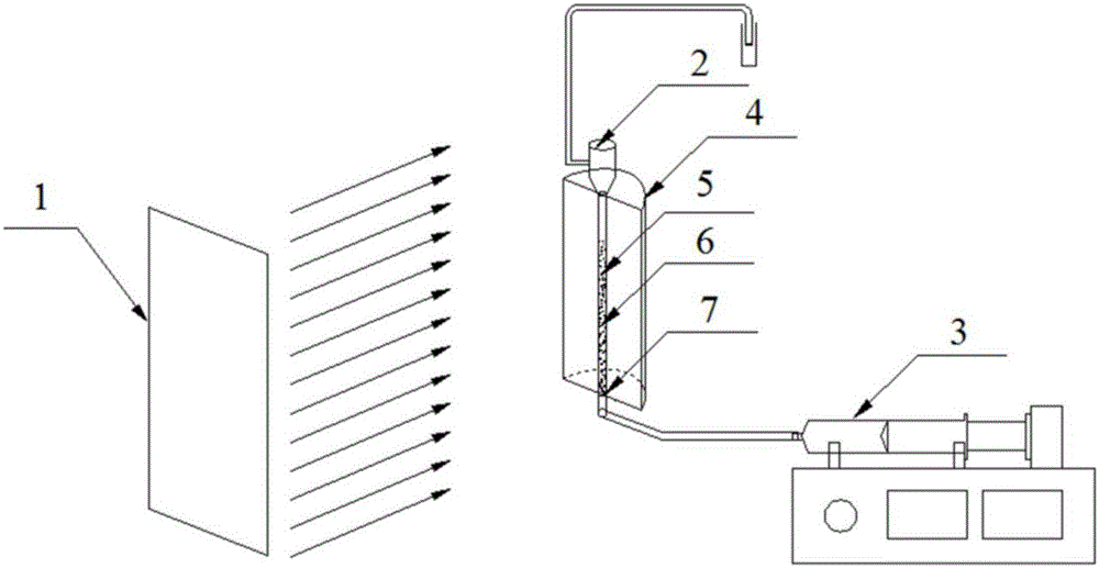
The invention discloses a photocatalysis miniature liquid-solid fluidized bed reactor. The liquid-solid fluidized bed reactor comprises a quartz tube and glass beads placed in the quartz tube, the inner wall of the quartz tube and the surfaces of the glass beads are loaded with catalyst films, a liquid inlet is formed in the bottom of the quartz tube, a screen is arranged on the liquid inlet and used as a liquid distributor, and the liquid inlet is connected with an outlet of a liquid micro-injection pump through a pipeline; an expanding section is arranged at the top of the quartz tube, and a liquid outlet is formed in the expanding section and connected with an outlet pipeline so that reacted liquid can flow out of the reactor; a light source is arranged in front of the quartz tube, and a reflecting cover of a parabola type is arranged behind the quartz tube. The mass transfer resistance of the photocatalysis miniature liquid-solid fluidized bed reactor is small, and the mass transfer is increased by one magnitude order than that in a common single-phase microreactor.
Description
technical field [0001] The invention relates to the technical field of photocatalysis, in particular to the micro liquid-solid fluidized bed reactor technology. Background technique [0002] Microreactors have been used in the field of photocatalysis since their appearance in the 1990s. The characteristic size of photocatalytic microreactor is below 1mm (Chem.Eng.Sci.,2001,(56):293-303), which has many advantages, such as high specific surface area (>10000m 2 / m 3 ), high mass and heat transfer rates, and small uniform light attenuation (Lab on a Chip, 2001, 1(1): 22-28; AIChE J., 2007, 53(3): 695-700; Chem. Eng. J., 2008, 135(4):S303-S308). At the same time, it also has some obvious disadvantages. First, compared with the suspended catalyst particles, the phase boundary area of the catalyst loaded on the inner surface of the microchannel is very small; second, the characteristic size of the microreactor determines that its illuminated area is very small, and the tr...
Claims
Login to View More Application Information
Patent Timeline
 IPC IPC(8): B01J19/00B01J19/12
CPCB01J19/0093B01J19/12B01J2219/00835B01J2219/00934
Inventor 刘明言杨中国王晓云
Owner TIANJIN UNIV
Features
- R&D
- Intellectual Property
- Life Sciences
- Materials
- Tech Scout
- Unparalleled Data Quality
- Higher Quality Content
- 60% Fewer Hallucinations
Learn More Browse by: Latest US Patents, China's latest patents, Technical Efficacy Thesaurus, Application Domain, Technology Topic, Popular Technical Reports.
© 2025 PatSnap. All rights reserved.Legal|Privacy policy|Modern Slavery Act Transparency Statement|Sitemap|About US| Contact US: help@patsnap.com