
Permanent magnet synchronous motor direct driven energy-saving ball mill

A permanent magnet synchronous motor and direct drive technology, applied in the direction of controlling mechanical energy, electrical components, electromechanical devices, etc., can solve the problems of reduced efficiency, cumbersome transmission mechanism, and loss of transmission mechanism, so as to reduce frictional resistance and improve Energy saving and emission reduction, the effect of improving production efficiency

Inactive Publication Date: 2016-12-14
CHENGDU MAOYUAN TECH
View PDF12 Cites 10 Cited by
  • Summary
  • Abstract
  • Description
  • Claims
  • Application Information

AI Technical Summary

Problems solved by technology

[0003] The existing ball mill needs to be equipped with a cumbersome transmission mechanism. The output shaft of the motor drives the rotating shaft of the drum to rotate through the coupling. Since the motor and the coupling need to occupy a certain extra area, the existing ball mill occupies a large area.
When the output shaft of the motor drives the rotary shaft of the drum to rotate through the coupling, the stability of the existing ball mill is not good, the gears are easy to be damaged, and the maintenance is frequent
More importantly, the transmission mechanism will suffer loss during operation, and the efficiency will decrease

Method used


Image

  • Permanent magnet synchronous motor direct driven energy-saving ball mill
  • Permanent magnet synchronous motor direct driven energy-saving ball mill
  • Permanent magnet synchronous motor direct driven energy-saving ball mill

Examples


Embodiment 1

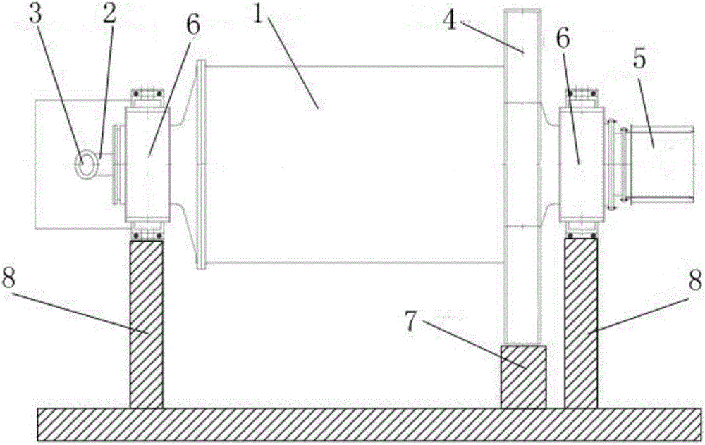
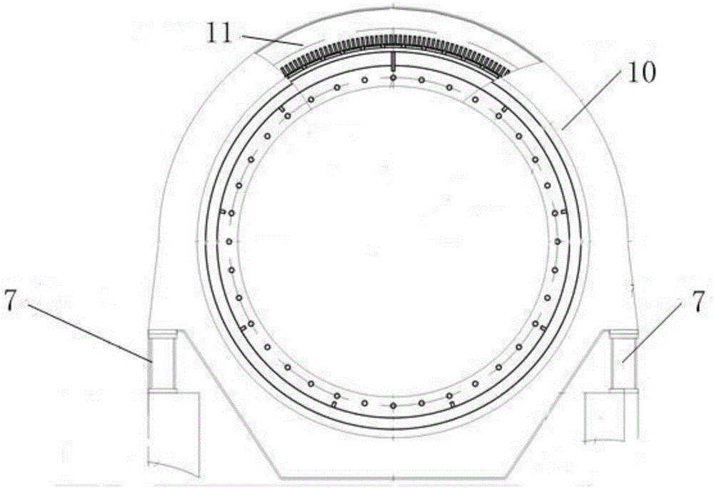
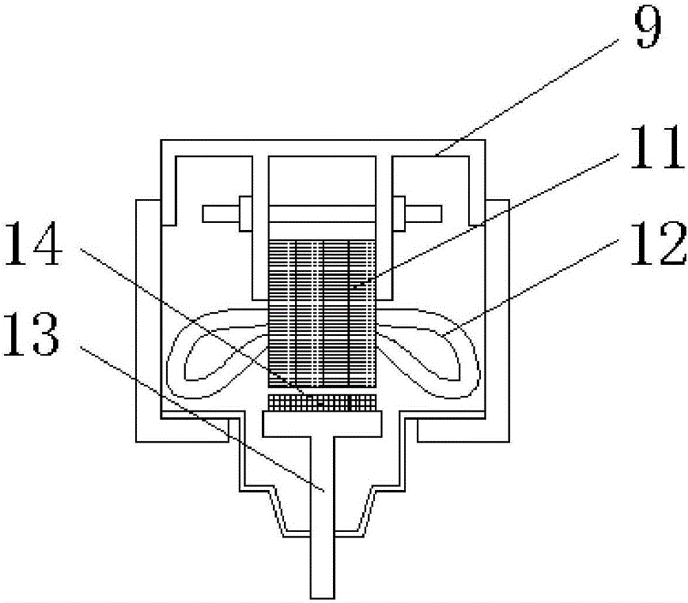
[0021] see figure 1 , figure 2 and image 3 , a permanent magnet synchronous motor direct-drive energy-saving ball mill, including a drum 1, the two ends of the drum 1 are respectively provided with a feed shaft 2 and a discharge end 5, and the drum 1 is sleeved in a sliding bearing 6 , the sliding bearing 6 is placed on the bearing support frame 8, the surface of the drum 1 is covered with a ring motor 4, the ring motor 4 is placed on the motor bracket 7, and the ring motor 4 includes a casing 10, a stator and The rotor, the casing 10 is fixed on the motor bracket 7, the stator core 11 and the stator winding 12 are arranged in the stator, the stator is fixed inside the casing 10, and the rotor is fixedly connected with the pole bracket 13 The permanent magnet poles 14, the pole bracket 13 is fixed on the shell of the drum 1.

[0022] In the present invention, the material enters from the feed shaft 2 and is discharged from the discharge end 5 . The rotating drum 1 is set...


PUM


Abstract

The invention discloses a permanent magnet synchronous motor direct driven energy-saving ball mill. The permanent magnet synchronous motor direct driven energy-saving ball mill comprises a rotating drum, wherein a feeding end and a discharge end are respectively arranged at the two ends of the rotating drum; the rotating drum is arranged inside sliding bearings in a sleeving manner; the sliding bearings are arranged on bearing support frames; a ring motor sleeves the surface of the rotating drum; the ring motor is arranged on a motor bracket; the ring motor comprises a motor shell, a stator and a rotor; the motor shell is fixed to the motor bracket; a stator iron core and a stator winding are arranged inside the stator; the stator is fixedly arranged inside the motor shell; the rotor is a permanent magnet magnetic pole fixedly connected with a magnetic pole bracket; and the magnetic pole bracket is fixedly arranged on an outer shell of the rotating drum. According to the permanent magnet synchronous motor direct driven energy-saving ball mill, the permanent magnet magnetic pole is directly mounted on the surface of the rotating drum, the ring motor directly drives the rotating drum, a complex transmission mechanism is avoided, the operation is more stable, transmission loss is avoided, the floor space is smaller, one workshop can be equipped with more ball mills, the production efficiency is improved, and energy conservation and emission reduction are facilitated.

Description

technical field [0001] The invention relates to the field of material crushing mechanical equipment, specifically refers to a permanent magnet synchronous ring motor made of permanent magnet poles installed on the surface of the drum, an annular stator core and windings, directly driving the ball mill to drive the permanent magnet poles on the drum . Background technique [0002] The ball mill is a kind of equipment for crushing materials. Its basic principle is to use the rotating force to lift the steel balls in the cylinder to a certain height and drop them on the materials. The materials are crushed by the mutual contact between the steel balls and the materials. [0003] Existing ball mills need to be equipped with a cumbersome transmission mechanism. The output shaft of the motor drives the rotary shaft of the drum to rotate through the coupling. Since the motor and the coupling need to occupy a certain additional area, the existing ball mill occupies a large area. Wh...

Claims


Application Information

Patent Timeline
Patent Type & Authority Applications(China)
IPC IPC(8): B02C17/10B02C17/24H02K7/14H02K5/167H02K11/21
CPCB02C17/10B02C17/24H02K5/1672H02K7/14
Inventor 陆可鞠林睿王家璐张霆郭冀岭
Owner CHENGDU MAOYUAN TECH
Learn More