Progressively increased tooth pitch traveling wave magnetic field casting equipment and casting method

A technology of traveling wave magnetic field and casting equipment, which is applied in the field of wide pitch traveling wave magnetic field casting equipment and casting, which can solve the problems of prone to dents on the surface and poor melt flow stability, and achieve the elimination of surface dents, stable mold filling, Effect of improving productivity and surface quality

Inactive Publication Date: 2016-12-14
CHANGZHOU INST OF MECHATRONIC TECH
View PDF5 Cites 1 Cited by
  • Summary
  • Abstract
  • Description
  • Claims
  • Application Information

AI Technical Summary

Problems solved by technology

[0005] The purpose of the present invention is to provide a wide pitch traveling wave magnetic field casting equipment and casting method to solve the technical problems of poor melt flow stability and prone to dents on the surface during the solidification process of the traditional mold filling process

Method used


Image

  • Progressively increased tooth pitch traveling wave magnetic field casting equipment and casting method
  • Progressively increased tooth pitch traveling wave magnetic field casting equipment and casting method
  • Progressively increased tooth pitch traveling wave magnetic field casting equipment and casting method

Examples


Embodiment 1

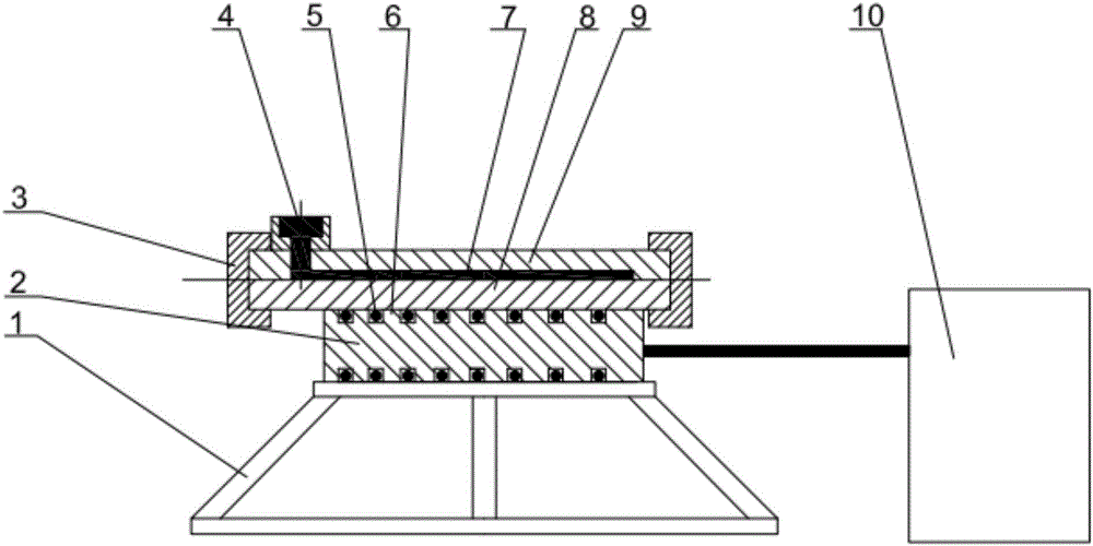
[0024] Such as figure 1 As shown, the present embodiment 1 provides a casting equipment, including: a horizontally placed metal melt filling device, a traveling wave magnetic field electromagnetic sensor located at the bottom of the metal melt filling device; wherein the traveling wave magnetic field electromagnetic The magnetic inductor generates a traveling wave magnetic field by loading current, so that the molten metal in the molten metal filling device moves at a constant speed to fill the mold.

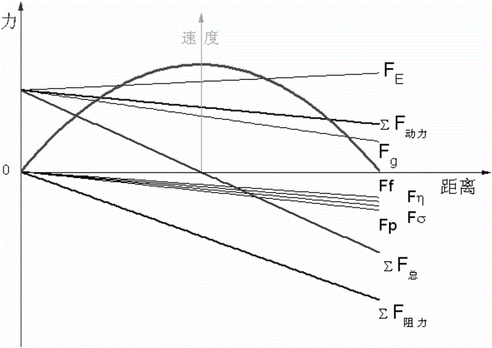
[0025] Working principle of the present invention: as figure 2 As shown, the forces received by the alloy melt during the filling process include the static pressure head pressure Fg, the electromagnetic propulsion force FE, the friction force Ff of the cavity, the internal friction force Fη of the melt, and the gas counterpressure Fp in the cavity and surface tension Fσ six forces, of which the static pressure head pressure Fg, electromagnetic propulsion FE is the driving for...

Embodiment 2

[0033] On the basis of embodiment 1, this embodiment 2 provides a casting method.

[0034] The casting method comprises: making the molten metal in the molten metal filling device move at a uniform speed to fill the mold through a traveling wave magnetic field.

[0035] Further, the traveling wave magnetic field is a decreasing traveling wave magnetic field, and is generated by a traveling wave magnetic field electromagnetic inductor, that is, the traveling wave magnetic field electromagnetic inductor decreases the electromagnetic propulsion obtained by the metal melt after being energized.

[0036] As a preferred implementation of the traveling wave magnetic field electromagnetic inductor, the traveling wave magnetic field electromagnetic inductor includes: an iron core 2, a plurality of teeth for coil winding are distributed on the outer circumference of the iron core, that is, the coil is embedded Between each tooth; and according to the moving direction of the molten metal...


PUM


Abstract

The invention relates to progressively increased tooth pitch traveling wave magnetic field casting equipment and a casting method. The casting equipment comprises a horizontally arranged metal melt filling device and a traveling wave magnetic field electromagnetic inductor located at the bottom of the metal melt filling device, wherein the traveling wave magnetic field electromagnetic inductor generates a traveling wave magnetic field by loading current, so that a metal melt in the metal melt filling device moves at constant speed for filling. By the use of the progressively increased tooth pitch traveling wave magnetic field casting equipment and the casting method, the progressively decreased traveling wave magnetic field can be obtained, so that alloy melt filling is steady, and recesses in the surface of a melt solidification process are eliminated; the production efficiency and the surface quality of traveling wave magnetic field casting can be effectively improved; and the technical obstacles are cleared away to comprehensively popularize electromagnetic casting.

Description

technical field [0001] The invention relates to casting equipment and a casting method of traveling wave magnetic field with widening tooth pitch. Background technique [0002] The problem encountered by general casting technology for the production of components with large specific surface area is that the temperature of the melt drops rapidly, causing defects that cannot be completely formed. This contradiction can be resolved by increasing the pouring temperature and the preheating temperature of the mold, but the deterioration of the structure and performance of the component will follow. [0003] In order to fundamentally solve the casting problem of components with large specific surface area, both "heat" and "force" must be considered together. While ensuring that the temperature of the metal melt decreases slowly, it is also necessary to increase the driving force of the metal flow. There are many ways to improve the driving force of metal melt, such as mechanical p...

Claims


Application Information

Patent Timeline
Patent Type & Authority Applications(China)
IPC IPC(8): B22D27/02
CPCB22D27/02
Inventor 吕国伟欧阳文韬陈海华沈银锋李姚凯吴燹
Owner CHANGZHOU INST OF MECHATRONIC TECH
Why Eureka
Try Eureka