Laser precision micro machining device and method of light guide plate

A technology of microfabrication and light guide plate, applied in the direction of measuring device, laser welding equipment, metal processing equipment, etc., can solve the problems of different quality of laser light source, low processing efficiency, high defect rate of light plate scattering network, and reduce labor cost , improve efficiency, and achieve a high degree of automation

Active Publication Date: 2016-12-14
QINGDAO TECHNOLOGICAL UNIVERSITY
View PDF5 Cites 9 Cited by
  • Summary
  • Abstract
  • Description
  • Claims
  • Application Information

AI Technical Summary

Problems solved by technology

[0004] At present, the manufacturing methods of light guide plate scattering dots include mold forming method, ink printing method and laser processing method, etc. The existing laser processing equipment has different quality of laser light source, which easily leads to high defect rate and low processing efficiency of light guide plate scattering dots The problem

Method used


Image

  • Laser precision micro machining device and method of light guide plate
  • Laser precision micro machining device and method of light guide plate
  • Laser precision micro machining device and method of light guide plate

Examples


Embodiment Construction

[0041] The laser precision micromachining device and the processing method of the light guide plate of the present invention will be described in detail below in conjunction with the accompanying drawings.

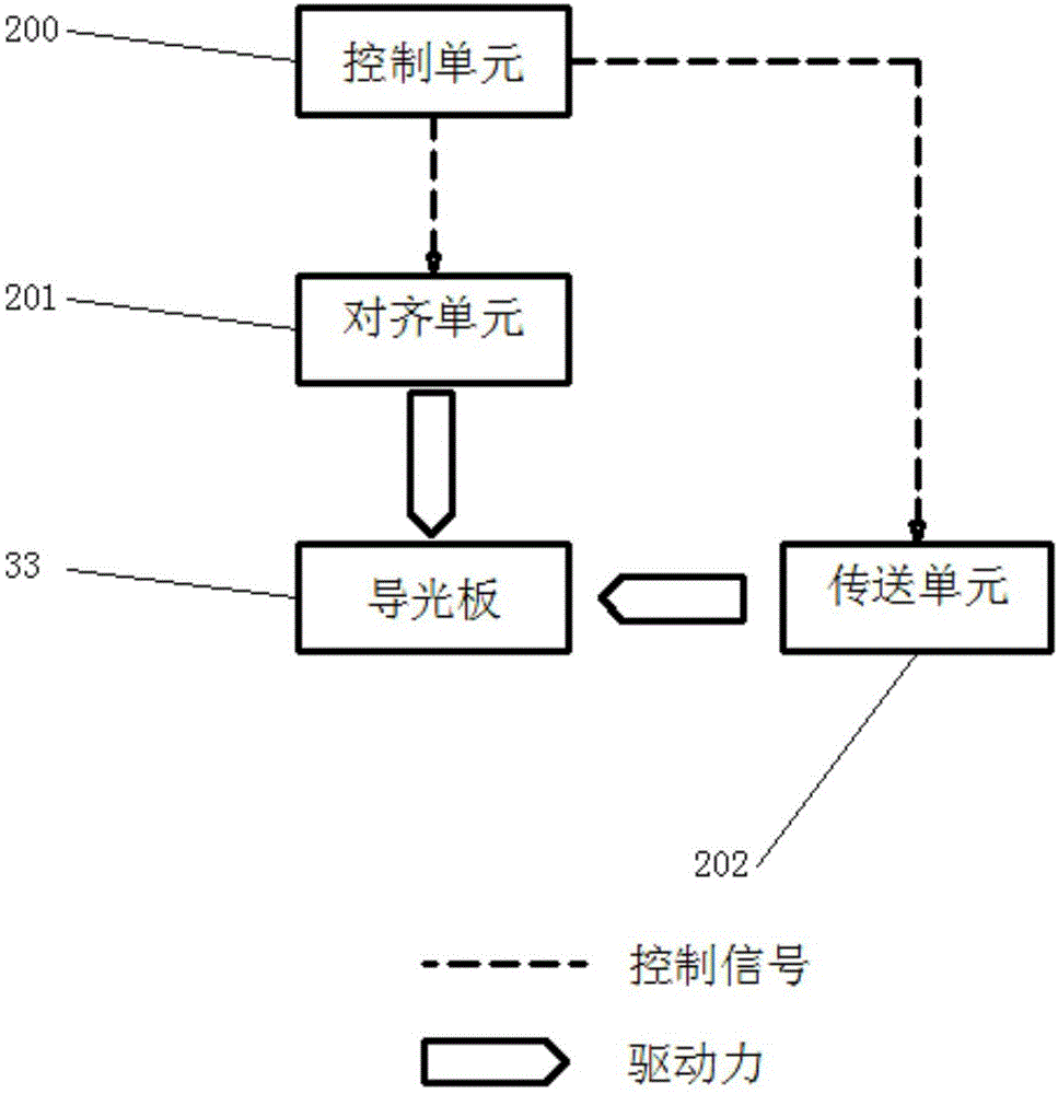
[0042] Such as figure 1 As shown, it is a relationship diagram between the transmission unit, the automatic alignment unit and the control unit of the light guide plate laser precision micromachining device of the present invention;

[0043] It includes: a transmission unit 202: a mechanism for transmitting the light guide plate for processing scattered dots; an automatic alignment unit 201: a mechanism for adjusting the position of the processed light guide plate; a control unit 200: used for controlling each unit;

[0044] The sending unit 202 includes: image 3 , rollers 2, 3, and a conveyor belt 4, which are used to transport the light guide plate 34 for processing during the entire processing process.

[0045] The automatic alignment unit 201 includes: Figure 5 , ...


PUM


Abstract

The invention discloses a laser precision micro machining device and method of a light guide plate. The laser precision micro machining device comprises a laser generating unit, a moving unit, an automatic alignment unit, an induction unit and a control unit, wherein the laser generating unit is used for generating laser required by machining; the moving unit is used for conveying the light guide plate required by machining; the automatic alignment unit is used for adjusting the position of the light guide plate required by machining; the induction unit is used for locating the light guide plate required by machining; and the control unit is used for controlling the laser generating unit, the moving unit, the automatic alignment unit and the an induction unit in a laser machining process. According to a dotting device of the light guide plate by utilizing laser, the light guide plates of different sizes can be machined by virtue of a full-automatic system, the machining precision and the machining efficiency of the light guide plates are greatly improved, and the defective rate of machined parts is effectively reduced.

Description

technical field [0001] The invention discloses a laser precision micromachining device and method for a light guide plate, belonging to the field of high-end laser manufacturing equipment and advanced processing technology. Background technique [0002] Performance parameters such as brightness and uniformity of the backlight module directly affect the image quality of a liquid crystal display (LCD). Liquid crystal displays have more and more stringent requirements in terms of brightness and chromaticity, so the requirements for backlight modules are also getting higher and higher. The role of the light guide plate is to guide the scattering direction of light to improve the brightness and control the uniformity of the brightness. Therefore, the design and manufacture of the light guide plate is one of the key technologies of the backlight module. In the process of developing the light guide plate, the performance of the light guide plate is still determined by the distribu...

Claims


Application Information

Patent Timeline
Patent Type & Authority Applications(China)
IPC IPC(8): B23K26/362B23K26/70B23K26/08B23K26/0622G01B17/02
CPCB23K26/0622B23K26/08B23K26/361B23K26/70B23K26/703G01B17/02
Inventor 孙树峰刘方祥王萍萍孙术彬庄梅
Owner QINGDAO TECHNOLOGICAL UNIVERSITY
Why Eureka
Try Eureka