Eureka AIR delivers breakthrough ideas for toughest innovation challenges, trusted by R&D personnel around the world.

Protective rubber for later machining of machining equipment surface

A machining and rubber technology, applied in metal processing equipment, manufacturing tools, used abrasive processing devices, etc., can solve the problems of aging of the protective cover, affecting the service life of the protective cover, time-consuming and laborious, etc. The effect of work efficiency and protection quality

Inactive Publication Date: 2016-12-14
天津龙嘉科技有限公司
View PDF0 Cites 0 Cited by
  • Summary
  • Abstract
  • Description
  • Claims
  • Application Information

AI Technical Summary

Problems solved by technology

Since the sandblasting process will generate a lot of dust and noise, and people often operate in a confined space, it poses a great threat to health. In order to solve this problem, a device for automatic sandblasting by machinery has been developed, but due to the The whole is controlled mechanically, and because the interior of the device is sealed as a whole, and the space in the sealing area is small, during the sandblasting operation, the sprayed powder or sand flow is easy to adhere to the protective cover of the sandblasting system, and after a long period of enrichment Afterwards, not only is it inconvenient to clean up, but it will even cause the aging of the protective cover and affect the service life of the protective cover itself.
In recent years, to prevent damage to the machined surface during sandblasting and painting, the method of fixing the plastic plate to the machined surface is mostly used. cleaning

Method used


Image

  • Protective rubber for later machining of machining equipment surface

Examples


Embodiment Construction

[0010] The specific implementation, structure, features and effects provided by the present invention will be described in detail below in conjunction with the accompanying drawings and preferred embodiments.

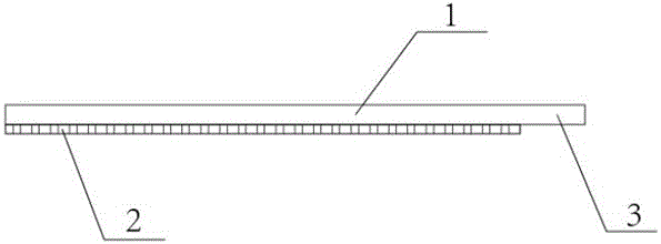
[0011] A protective rubber for post-processing of the machined surface of equipment, comprising: a protective rubber 1 and a rubber layer 2, wherein: the protective rubber 1 is made of EPDM rubber, and the shape of the protective rubber 1 is consistent with the surface of the machined equipment to be protected The shape is consistent; one end of the protective rubber 1 is provided with an easy-to-open area 3, the adhesive layer 2 is arranged on the bottom surface of the protective rubber 1, and no adhesive layer 2 is provided on the bottom surface of the easy-to-uncover area 3 of the protective rubber 1.

[0012] Further, the thickness of the protective rubber 1 is 2MM.

[0013] Further, the adhesive layer 2 is double-sided adhesive.

[0014] Compared with the prior ar...


PUM

PropertyMeasurementUnit
Thicknessaaaaaaaaaa

Abstract

Protective rubber for later machining of a machining equipment surface comprises a protective rubber body and a glue layer. An ethylene-propylene-diene monomer is adopted for the protective rubber body. The shape of the protective rubber body is the same as the shape of the machining equipment surface to be protected. An easy-to-open region is arranged at one end of the protective rubber body. The glue layer is arranged on the bottom surface of the protective rubber body. The bottom surface of the easy-to-open region of the protective rubber body is not provided with the glue layer. According to the protective rubber, in use, the protective rubber body is bonded to the machining equipment surface to the protected through the glue layer, then sand spraying or paint spraying is conducted, and the protective rubber is directly torn down overall through the easy-to-open region after sand spraying or paint spraying is completed; and in use, the protective rubber is bonded to the machining surface, the protective rubber is firm to bond and convenient and fast to use, the rubber is torn down directly after use, and the work efficiency and protection quality are improved.

Description

technical field [0001] The invention belongs to the field of equipment machining, and in particular relates to an improvement for machining equipment. Background technique [0002] The sand blasting process uses compressed air to form sand into a high-speed jet sand flow, which acts on the surface of the workpiece. Through the impact and grinding of the sand flow, the surface of the workpiece obtains a certain degree of cleanliness and different roughness; the sand blasting process is usually used on the surface of the workpiece Derusting, descaling, etc., are the treatment processes before painting and machining. Since the sandblasting process will generate a lot of dust and noise, and people often operate in a confined space, it poses a great threat to health. In order to solve this problem, a device for automatic sandblasting by machinery has been developed, but due to the The whole is controlled mechanically, and because the interior of the device is sealed as a whole, ...

Claims


Application Information

Patent Timeline
IPC IPC(8): B24C9/00
CPCB24C9/00
Inventor 李志刚
Owner 天津龙嘉科技有限公司
Why Eureka
Eureka Blog
Learn More