
Primary sealing device of compression plate type lightning protection oil storage tank

A technology for compressing plates and oil storage tanks, applied in packaging, transportation and packaging, containers, etc., can solve the problems of secondary environmental pollution, no lightning protection, poor compensation ability, etc., and achieve long service life and good sealing. , the effect of strong compensatory ability

Active Publication Date: 2018-08-10
吴戈 +1
View PDF5 Cites 0 Cited by
  • Summary
  • Abstract
  • Description
  • Claims
  • Application Information

AI Technical Summary

Problems solved by technology

[0016] The technical problem to be solved by the present invention is to provide a compression plate type lightning protection storage tank primary sealing device. The problem of fire accidents caused by derivation; the problem of poor compensation ability for the large change in the annular gap between the inner wall of the oil storage tank and the floating roof caused by the deformation of the inner wall of the oil storage tank and the uneven settlement of the foundation; the failure of the entire seal caused by local damage, The waste formed after damage is more, which will cause the problem of secondary pollution of the environment

Method used


Image

  • Primary sealing device of compression plate type lightning protection oil storage tank
  • Primary sealing device of compression plate type lightning protection oil storage tank
  • Primary sealing device of compression plate type lightning protection oil storage tank

Examples


Embodiment 1

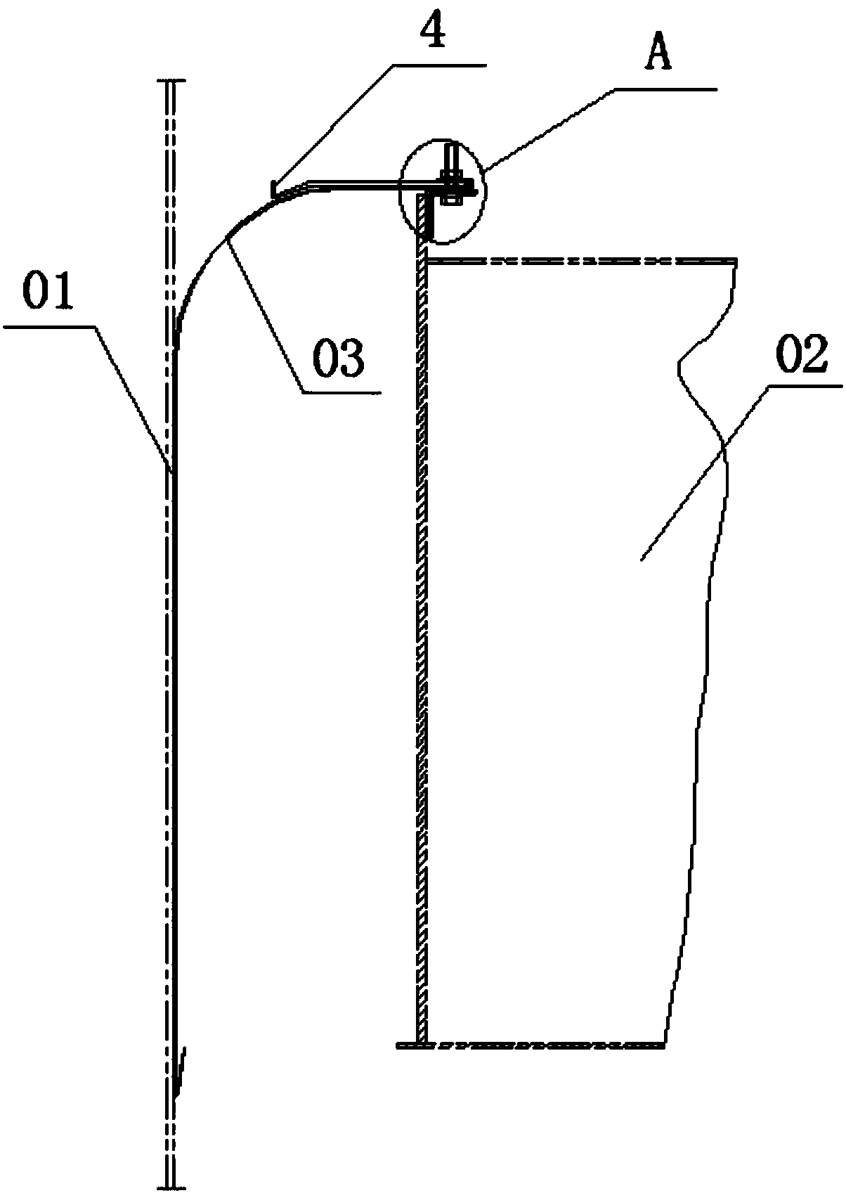
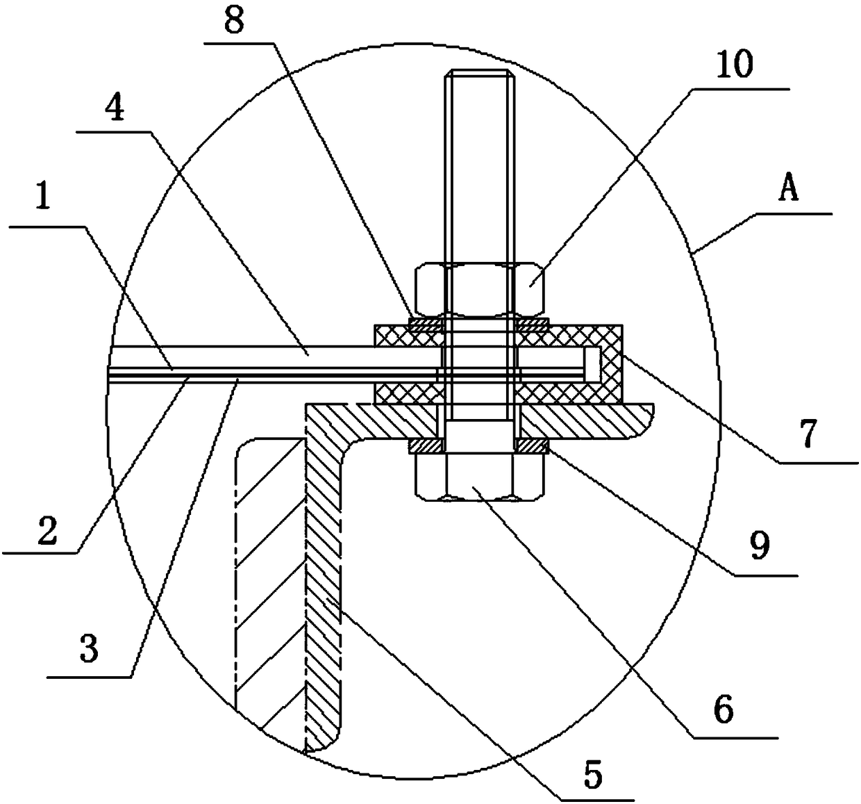
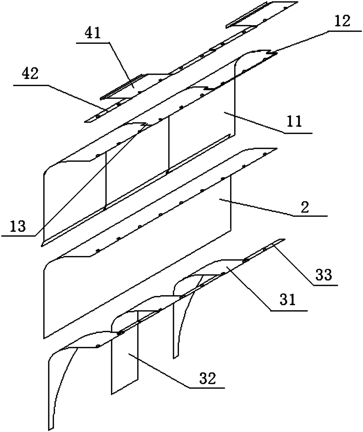
[0052] See figure 1 and figure 2 , the primary sealing device of the compression plate type lightning protection oil storage tank, including the ring-shaped compression plate 03 which is sequentially stacked by a stainless steel sealing plate 1, a gas barrier film 2 (polytetrafluoroethylene) and a stainless steel compression spring plate 3, and a buffer Plate 4, a plurality of connecting angle steels 5 and stainless steel connecting bolts 6; the buffer plate 4 is arranged above the inner end of the compression plate 03, and the inner end of the buffer plate 4 and the inner end of the compression plate 03 are laminated and wrapped with conductive rubber 7, The outer end of the compression plate 03 is bent downward, and the end surface of the stainless steel sealing plate 1 is close to the inner wall of the oil storage tank 01 under the elastic force of the stainless steel compression spring plate 3, and the immersion depth is not less than 100mm, and the vertical part of the c...

Embodiment 2

[0056] See Figure 4 and Figure 5 , the primary sealing device of the compression plate type lightning protection oil storage tank, including the ring-shaped compression plate 03 which is sequentially stacked by a stainless steel sealing plate 1, a gas barrier film 2 (polytetrafluoroethylene) and a stainless steel compression spring plate 3, and a buffer Plate 4, a plurality of connecting angle steels 5 and stainless steel connecting bolts 6; the buffer plate 5 is arranged above the inner end of the compression plate 03, and the inner end of the buffer plate 4 and the inner end of the compression plate 03 are laminated and wrapped with conductive rubber 7, The outer end of the compression plate 03 is bent downward, and the end surface of the stainless steel sealing plate 1 is close to the inner wall of the oil storage tank 01 under the elastic force of the stainless steel compression spring plate 3, and the depth of immersion is not less than 100mm. Part of it is fixedly con...

Embodiment 3

[0058] See Figure 6 and Figure 7 , the primary sealing device of the compression plate type lightning protection oil storage tank, including the ring-shaped compression plate 03 which is sequentially stacked by the stainless steel sealing plate 1, the gas barrier film 2 (polytetrafluoroethylene) and the stainless steel compression spring plate 3, and the ring-shaped The magnetic conductive rubber film 11, the buffer plate 4, a plurality of connecting angle steel 5 and stainless steel connecting bolts 6; the inner end of the compression plate 03 is wrapped with conductive rubber 7, the outer end of the compression plate 03 is bent downward and its stainless steel sealing plate 1 The end surface is close to the inner wall of the oil storage tank 01 under the elastic force of the stainless steel compression spring plate 3, the depth of immersion is not less than 100mm, the inner end of the magnetic conductive rubber film 11 is located above the inner end of the compression plat...


PUM


Abstract

The invention discloses a compressed plate type anti-lightning oil storage tank one-time sealing device, which comprises an annular compressed plate formed by sequentially overlaying a stainless steel seal plate, a breathable roofing underlayment and a stainless steel compressed spring plate, connection angles and a stainless steel connecting bolt. The inner end of the compressed plate is wrapped by an conductive rubber and is fixedly connected with a floating cover of an oil storage tank; the outer end part of the compressed plate is bent downwards; and the end face of the stainless steel seal plate closely clings to the inner wall of the oil storage tank under the elasticity function of the stainless steel compressed spring plate. According to the compressed plate type anti-lightning oil storage tank one-time sealing device provided by the invention, the compressed plate is reliably connected with the inner wall of the oil storage tank and the floating cover, and the breakover is favorable, so that an electric charge produced on the floating cover caused by lightning is guided into the inner wall of the oil storage tank through the compressed plate, and an effective anti-lightning function is realized; the stainless steel compressed spring plate plays a role in automatically returning the floating cover to the center; and the breakover between the floating cover and the compressed plate is favorable by utilizing materials such as a conductive paste and the conductive rubber, so that the electric charge produced on the floating cover caused by lightning can be beneficially guided into the inner wall of the oil storage tank quickly.

Description

technical field [0001] The invention relates to a floating roof sealing structure of an oil storage tank, in particular to a primary sealing device of a compressed plate type lightning protection oil storage tank. Background technique [0002] At present, the types of primary sealing devices for floating roofs of oil storage tanks are mainly soft foam seals, liquid-filled pipe seals, and steel sliding plate mechanical seals (section 8.9 of GB50341-2014). The main problems of the above-mentioned type of sealing device (refer to: spherical tank and large oil storage tank Chapter 5 P238~P246, edited by Xu Ying, Yang Yifan, Zhu Ping, etc., first edition in January 2005) are: [0003] (1) Soft foam seal: [0004] The foam material is easy to age, and the sealing effect will become worse and worse with the aging of the foam. After 5 years of use, the sealing effect will be greatly reduced; the inner wall of the oil storage tank and the floating roof caused by the deformation of t...

Claims


Application Information

Patent Timeline
Patent Type & Authority Patents(China)
IPC IPC(8): B65D88/46
CPCB65D88/46
Inventor 吴戈
Owner 吴戈
Learn More