Automotive exhaust flexible pipe
A technology of automobile exhaust and flexible pipes, which is applied in the direction of exhaust devices, noise reduction devices, engine components, etc., can solve the problems of poor shock resistance of exhaust pipes and affect service life, and achieve high production efficiency, prolong service life, and environmental flexibility The effect of increasing
- Summary
- Abstract
- Description
- Claims
- Application Information
AI Technical Summary
Problems solved by technology
Method used
Image

Examples
Embodiment 1
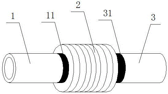
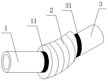
[0025] Such as Figure 1 to Figure 2 As shown, the present invention provides an automobile exhaust flexible pipe, which includes a first pipe 1 , a polyethylene corrugated pipe 2 communicating with the first pipe 1 and a second pipe 3 communicating with the polyethylene corrugated pipe 2 . By arranging the polyethylene corrugated pipe 2 between the first pipeline 1 and the second pipeline 3, the problem that the vibration of the exhaust pipe of the rigid vehicle is poor and affects the service life is effectively avoided due to the vibration during the running of the vehicle. .
[0026] Further, the connection between the first pipeline 1 and the polyethylene bellows 2 is provided with a first sealing sleeve 11; the connection between the second pipeline 3 and the polyethylene bellows 2 is provided with a second sealing sleeve 31; effectively preventing automobile exhaust Leakage, enhance the sealing of the car's exhaust pipe. The diameters of the first pipeline 1 and the s...
Embodiment 2
[0029] Polyethylene bellows for automotive exhaust flexible pipes, composed of 45% polyethylene, 5% bisphenol A polycarbonate, 5% polypropylene, 5% compatibilizer, 3% rigid masterbatch, 2% antioxidant, light 5% stabilizer, 5% graphene, 5% silane coupling agent, 2% 3-acetamido-5-methylisoxazole, 3% light shielding agent and 15% engineering plastics.
Embodiment 3
[0031] The processing method of polyethylene corrugated pipe for automobile exhaust flexible pipe, the steps are as follows:
[0032] 1) Mix the materials except engineering plastics (using the proportioning raw materials in Example 2) evenly, and heat to melt;
[0033] 2) Put the molten material into the twin-screw extrusion granulator, and set the processing temperature of each section of the extrusion granulator as follows: the temperature in zone 1-2 is 265°C, the temperature in zone 3-4 is 275°C, 5 The temperature in zone -6 is 285°C, the temperature in zone 7-8 is 305°C, the temperature in zone 9-10 is 310°C, the temperature of the die head is 100°C, the aspect ratio of the twin-screw is 32, the screw speed is 310 rpm, pelletize The speed is 15 times / min;
[0034] 3) Discharge, cool to room temperature, and then add engineering plastics to blend to obtain a blend;
[0035] 4) Granulate, heat and melt again, and then put it into the twin-screw extrusion granulator. The ...
PUM
 Abstract
Description
Claims
Application Information
 - R&D
- Intellectual Property
- Life Sciences
- Materials
- Tech Scout
- Unparalleled Data Quality
- Higher Quality Content
- 60% Fewer Hallucinations
Browse by: Latest US Patents, China's latest patents, Technical Efficacy Thesaurus, Application Domain, Technology Topic, Popular Technical Reports.
© 2025 PatSnap. All rights reserved.Legal|Privacy policy|Modern Slavery Act Transparency Statement|Sitemap|About US| Contact US: help@patsnap.com