
Stuffing box sealing structure, horizontal type stuffing box heat exchanger with same and installation method

A sealing structure and heat exchanger technology, which is applied in the sealing of engines, engine components, mechanical equipment, etc., can solve the problem of large gap between the tube sheet and the upper wall of the shell shell, the inability of the packing to expand normally, and the difficulty in installing the packing packing, etc. problem, to achieve the effect of eliminating uneven width, uniform width and convenient operation

Active Publication Date: 2016-12-14
XINDI ENERGY ENG TECH
View PDF6 Cites 0 Cited by
  • Summary
  • Abstract
  • Description
  • Claims
  • Application Information

AI Technical Summary

Problems solved by technology

According to the existing technology, in order to ensure that the tube bundle can penetrate the shell side shell smoothly, a relatively large gap needs to be left between the tube sheet and the inner diameter of the shell side shell, such as figure 2 , assuming that the theoretical gap between the tube sheet and the inner wall of the shell side is a, after the tube bundle is installed in place, the tube sheet will contact the lower surface of the inner wall of the shell under the gravity of the tube bundle, resulting in a gap between the tube sheet and the lower wall of the shell as 0, the gap with the upper wall of the shell increases to 2a ( image 3 shown in ), which also results in an uneven packing cavity width, with a width of "b+a" at the top and "b-a" at the bottom ( image 3 shown in)
This will lead to three adverse effects: 1. The gap between the tube sheet and the upper wall of the shell side shell is too large, and the packing will be squeezed into the gap when the packing is pressed, making the packing unable to expand normally and significantly reducing the sealing effect; 2. Due to Commonly used fillers (generally filler packing) have a constant width, and the uneven width of the filler cavity will make the installation of the filler packing difficult. During installation, the filler width must be artificially and irregularly changed to complete the installation of the filler, which increases the labor intensity. It will also destroy the original cross-sectional shape of the packing and reduce the sealing effect; 3. The packing seal is realized by the packing expansion by the extrusion of the packing gland, and the packing expansion capacity is limited. Because the width of the packing cavity is different from top to bottom, it will inevitably lead to the lower part of the shell. The wall is easy to achieve the sealing effect, but the upper wall is not easy to seal
[0004] The above problems have plagued designers and manufacturers of stuffing box heat exchangers for a long time. In view of this situation, the present invention proposes a new type of stuffing box structure to solve the above-mentioned technical problems that have plagued this field for a long time

Method used


Image

  • Stuffing box sealing structure, horizontal type stuffing box heat exchanger with same and installation method
  • Stuffing box sealing structure, horizontal type stuffing box heat exchanger with same and installation method
  • Stuffing box sealing structure, horizontal type stuffing box heat exchanger with same and installation method

Examples


Embodiment 1

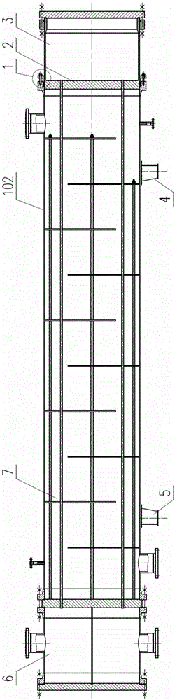
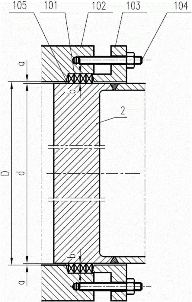
[0040] A stuffing box sealing structure for a horizontal heat exchanger, comprising: a retaining ring 106 arranged at the front end of the packing chamber between the tube sheet 2 and the shell side shell 102 and divided into two petals equally, and a retaining ring arranged in the packing chamber The packing 101 at the rear, and the packing gland 103 that seals the packing in the packing cavity. The packing gland 103 is fixed on the shell-side shell by studs 104, wherein the outer diameter of the retaining ring is the inner diameter of the shell-side shell -0.1mm, the inner diameter of the retaining ring is the outer diameter of the tube sheet +0.1mm, and the tube bundle is installed in the shell-side shell Finally, the gap c between the retaining ring and the tube sheet and the gap between the shell side and the shell are close to 0, and the actual width of the packing cavity is basically uniform up and down, so the sealing performance is excellent.

Embodiment 2

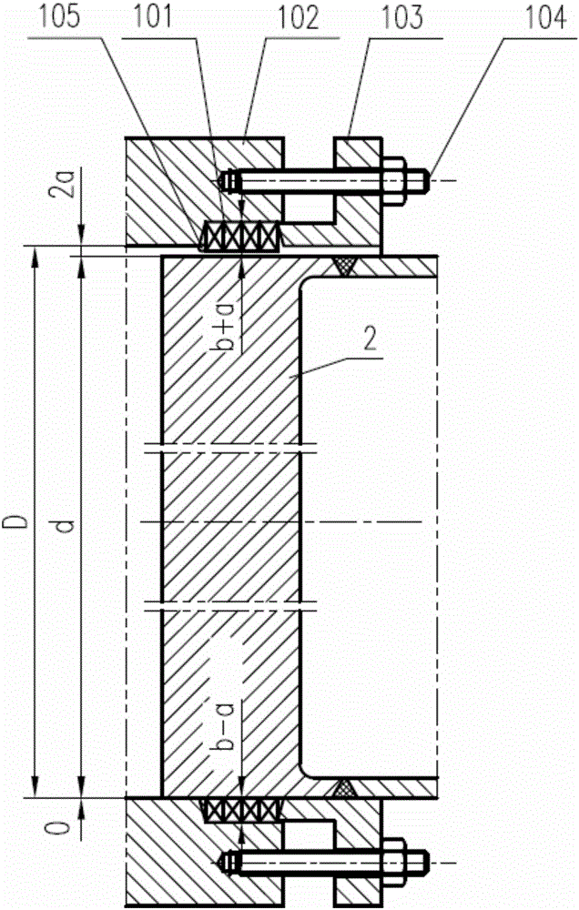
[0042] A stuffing box sealing structure for a horizontal heat exchanger, comprising: a retaining ring 106 arranged at the front end of the packing chamber between the tube sheet 2 and the shell side shell 102 and divided into two petals equally, and a retaining ring arranged in the packing chamber The packing 101 at the rear, and the packing gland 103 that seals the packing in the packing chamber. The packing gland 103 is fixed on the shell-side shell by studs 104, wherein the outer diameter of the baffle ring is equal to the inner diameter of the shell-side shell, and the inner diameter of the baffle ring is equal to the outer diameter of the tube sheet. After the tube bundle is installed in the shell-side shell, the baffle ring and the tube The gap c between the plate and the shell side is 0, the width of the packing cavity is completely uniform up and down, and the sealing performance is very good.

Embodiment 3

[0044] A stuffing box sealing structure for a horizontal heat exchanger, comprising: a retaining ring 106 arranged at the front end of the packing chamber between the tube sheet 2 and the shell side shell 102 and divided into two petals equally, and a retaining ring arranged in the packing chamber The packing 101 at the rear, and the packing gland 103 that seals the packing in the packing chamber. The packing gland 103 is fixed on the shell-side shell by studs 104, wherein the outer diameter of the retaining ring is the inner diameter of the shell-side shell -0.1mm, the inner diameter of the retaining ring is the outer diameter of the tube sheet +0.1mm, and the tube bundle is installed in the shell-side shell Finally, the gap c between the retaining ring and the tube sheet and the gap between the shell side and the shell are close to 0, and the actual width of the packing cavity is basically uniform up and down, so the sealing performance is excellent. At the same time, three ...


PUM


Abstract

The invention relates to a stuffing box sealing structure for a horizontal type heat exchanger, the horizontal type stuffing box heat exchanger with the structure and an installation method. The stuffing box sealing structure comprises a baffle ring, stuffing and a stuffing gland, wherein the baffle ring is arranged at the front-most end of a stuffing cavity located between a tube sheet and a shell pass shell and divided into two petals; the stuffing is arranged behind the baffle ring in the stuffing cavity; and the stuffing gland seals the stuffing into the stuffing cavity. By the adoption of the structure, the problem that the width of the stuffing cavity is uneven and the problem that the gap between the tube sheet and the inner wall of the shell pass shell is also uneven are removed, and the sealing effect is improved. The stuffing box sealing structure not only can pass a conventional hydraulic test but also can pass various leakage tests (like the airtightness test and ammonia leakage test) easily. Meanwhile, by means of the stuffing box sealing structure, the stuffing can be placed into the stuffing cavity more easily, operation is simple, the labor intensity of workers is lowered, and the replacing frequency of the stuffing can be effectively decreased.

Description

technical field [0001] The invention relates to a stuffing box sealing structure for a horizontal heat exchanger, a horizontal stuffing box heat exchanger including the structure and an installation method. Background technique [0002] The stuffing box sealing structure is a basic sealing mechanism of the heat exchanger. Due to the stuffing box sealing, the tube bundle of the heat exchanger can be freely expanded and contracted in the axial direction of the shell, and there will be no thermal deformation difference between the shell wall and the tube wall. of thermal stress. At the same time, compared with the floating head heat exchanger, the stuffing box heat exchanger has a simpler structure, convenient processing and manufacturing, saves materials, and is relatively low in cost. The tube bundle can be drawn out from the cylinder, and the inside and between the tubes can be cleaned, which is convenient for maintenance. However, the sealing structure of the stuffing box ...

Claims


Application Information

Patent Timeline
Patent Type & Authority Applications(China)
IPC IPC(8): F16J15/10
CPCF16J15/104
Inventor 谷海林张利伟武艳芳杨洪娟寇伟伟徐化周门继军刘金超楚洁璞韩博
Owner XINDI ENERGY ENG TECH
Features
  • Generate Ideas
  • Intellectual Property
  • Life Sciences
  • Materials
  • Tech Scout
  • Unparalleled Data Quality
  • Higher Quality Content
  • 60% Fewer Hallucinations
Learn More