Huyghens source antenna

An antenna and excitation source technology, applied in the field of end-fired low-profile Huygens source antennas, can solve the problems of high antenna profile and low radiation efficiency, and achieve the effect of simple and compact structure, high radiation efficiency, and easy processing and manufacturing

Active Publication Date: 2016-12-14
CHONGQING UNIV +1
View PDF9 Cites 3 Cited by
  • Summary
  • Abstract
  • Description
  • Claims
  • Application Information

AI Technical Summary

Problems solved by technology

[0004] The purpose of this disclosure is to provide a Huygens source antenna, which is used to solve the existing problems of high antenna profile and low radiation efficiency

Method used


Image

  • Huyghens source antenna
  • Huyghens source antenna
  • Huyghens source antenna

Examples


Embodiment Construction

[0033] Reference will now be made in detail to the exemplary embodiments, examples of which are illustrated in the accompanying drawings. When the following description refers to the accompanying drawings, the same numerals in different drawings refer to the same or similar elements unless otherwise indicated. The implementations described in the following exemplary examples do not represent all implementations consistent with the present disclosure. Rather, they are merely examples of apparatuses and methods consistent with aspects of the present disclosure as recited in the appended claims.

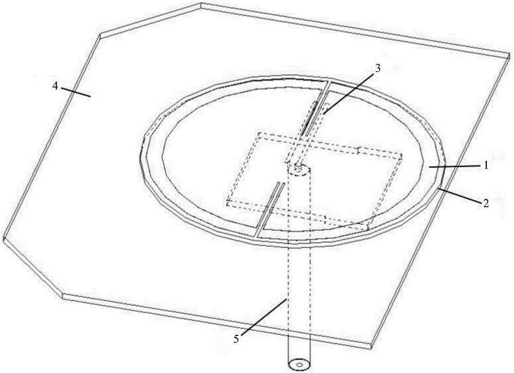
[0034] figure 1 is a schematic structural diagram of a Huygens source antenna shown according to an exemplary embodiment, as shown in figure 1 As shown, the Huygens source antenna consists of:

[0035] a dielectric substrate 2, comprising opposite first and second surfaces;

[0036] The magnetic dipole 1 is attached to the first surface of the dielectric substrate 2;

[0037] an ex...


PUM


Abstract

The invention discloses a huyghens source antenna. The huyghens source antenna comprises a dielectric substrate, a magnetic dipole, an excitation source, an electric dipole and a coaxial cable, wherein the dielectric substrate comprises a first surface and a second surface which are opposite to each other, the magnetic dipole is in contact with the first surface of the dielectric substrate, the excitation source is in contact with the second surface of the dielectric substrate, the electric dipole is arranged at one side of the second surface of the dielectric substrate, is arranged in parallel to the dielectric substrate and is separated from the dielectric substrate, and the coaxial cable is arranged in a groove hole formed in the electric dipole in a penetrating way and is connected with the excitation source. The huyghens source disclosed by the invention has the characteristics of low profile and favorable end emission radiation, is simple and compact in structure and is easy to process and fabricate, and the problems of relatively high profile, relatively low radiation efficiency and the like of an existing antenna are solved.

Description

technical field [0001] The present disclosure relates to the field of antennas, in particular to an end-fire low-profile Huygens source antenna applied to a wireless power transmission system. Background technique [0002] With the advent of the networked and intelligent information age, various electronic and electrical equipment have been integrated into all aspects of society, which has increased the dependence on energy. At present, cables and batteries are mainly used to supplement energy for equipment. These two methods seriously restrict the development of equipment towards portability and miniaturization. Especially in the complex power supply environment and the need for long-term battery life, this contradiction is even more prominent. The wireless power transmission system gets rid of the limitations of traditional cables and battery power supply, and can provide timely, convenient and quick energy supplement to the equipment to make the equipment work normally. ...

Claims


Application Information

Patent Timeline
Patent Type & Authority Applications(China)
IPC IPC(8): H01Q1/38
CPCH01Q1/38Y02D30/70
Inventor 唐明春周博雅石婷李梅刘书君
Owner CHONGQING UNIV
Why Eureka
Try Eureka