Devices, systems, and method for power control of dynamic electric vehicle charging systems

A technology for electric vehicles and charging power, applied in electric vehicle charging technology, electric vehicles, charging stations, etc., can solve problems such as bulkiness and inconvenient connectors

Active Publication Date: 2016-12-14
WITRICITY CORP
View PDF3 Cites 7 Cited by
  • Summary
  • Abstract
  • Description
  • Claims
  • Application Information

AI Technical Summary

Problems solved by technology

Cables and similar connectors can sometimes b...

Method used


Image

  • Devices, systems, and method for power control of dynamic electric vehicle charging systems
  • Devices, systems, and method for power control of dynamic electric vehicle charging systems
  • Devices, systems, and method for power control of dynamic electric vehicle charging systems

Examples


Embodiment Construction

[0024] The detailed description set forth below in connection with the accompanying drawings is intended as a description of certain implementations of the invention and is not intended to be the only implementations in which the invention may be practiced. The term "exemplary" is used throughout this description to mean "serving as an example, instance, or illustration" and is not necessarily to be construed as superior or superior to other exemplary implementations. The specific implementations include specific details for the purpose of providing a thorough understanding of the disclosed implementations. In some instances, devices are shown in block diagram form.

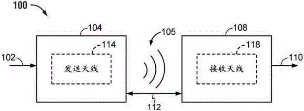
[0025] Wirelessly transferring power may refer to transferring any form of energy associated with an electric, magnetic, electromagnetic field, or otherwise, from a transmitter to a receiver without the use of physical electrical conductors (eg, power may be transferred through free space). Power output into a w...


PUM


Abstract

Systems, methods, and apparatus are disclosed for wirelessly charging an electric vehicle. In one aspect, a method of wirelessly charging an electric vehicle is provided. The method includes, obtaining a request from the electric vehicle for a level of charging power to be delivered from a power transmitter to the electric vehicle via a charging field. The method further includes controlling a current or voltage of the power transmitter based on a power efficiency factor and the requested level of charging power.

Description

technical field [0001] The present application relates generally to wireless power charging of chargeable devices, such as electric vehicles. Background technique [0002] Rechargeable systems, such as vehicles, have been introduced that include motion power derived from electrical power received from an energy storage device, such as a battery. For example, hybrid electric vehicles include on-board chargers that use power from the vehicle's brakes and a conventional electric motor to charge the vehicle. Purely electric vehicles typically receive power from other sources for charging the battery. It is often proposed to charge battery electric vehicles from some type of wired alternating current (AC), such as a household or commercial AC power source. A wired charging connection requires a cable or other similar connector that physically connects to a power source. Cables and similar connectors can sometimes be inconvenient or bulky and have other disadvantages. It would...

Claims


Application Information

Patent Timeline
IPC IPC(8): B60L11/18H02J5/00H02J7/02H02J50/10
CPCH02J5/005H02J7/025B60L53/12Y02T10/7072Y02T90/14B60L53/00H02J50/12B60L53/126B60L53/122B60L53/66H02J7/00034Y02T90/12Y02T90/16Y02T10/70H02J50/402H02J50/005H02J50/80H02J50/90H02J7/0042B60L53/60H02J7/007B60Y2200/91B60Y2200/92B60L53/305H02J7/00
Inventor N·A·科凌C·A·卡马斯卡拉米雷茨J·贝亚弗C-Y·黄M·B·布迪亚M·L·G·基辛
Owner WITRICITY CORP
Why Eureka
Try Eureka