Multi-station concrete component forming machine

A concrete and molding machine technology, applied in ceramic molding machines, molding indenters, manufacturing tools, etc., can solve the problems affecting the strength and shape of concrete components, the components are prone to honeycomb pits, and the service life of equipment is shortened, and achieves high rigidity. , Not easy to deform or tilt, improve strength and quality

Active Publication Date: 2018-08-24
SHANDONG JIANZHU UNIV
View PDF8 Cites 0 Cited by
  • Summary
  • Abstract
  • Description
  • Claims
  • Application Information

AI Technical Summary

Problems solved by technology

But this multi-station concrete member forming machine mainly has the following disadvantages: (1) only after all the molds have completed the extrusion process, the concrete member can be taken out, then poured into concrete, and then the next operation is carried out, the production process is still discontinuous, The efficiency is low; (2) During the extrusion process, the pressure is high, and the cantilever beam structure is prone to deformation, so that the concrete in the mold is under insufficient pressure and the pressure is uneven, thereby affecting the strength and shape of the concrete component, and it is also easy to Cause equipment damage and shorten the service life of equipment; (3) In actual use, since the vibration motor is installed on the side wall or bottom plate of the mold, and the fluidity of the concrete in the mold is poor, the vibration process needs to be expensive in actual use. For a long time, the vibration effect is often unsatisfactory, and the components are prone to honeycomb pitting, which reduces their strength and quality.

Method used


Image

  • Multi-station concrete component forming machine
  • Multi-station concrete component forming machine
  • Multi-station concrete component forming machine

Examples


Embodiment Construction

[0036] The present invention will be further described below in conjunction with accompanying drawing:

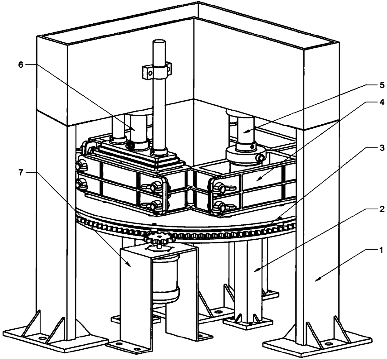
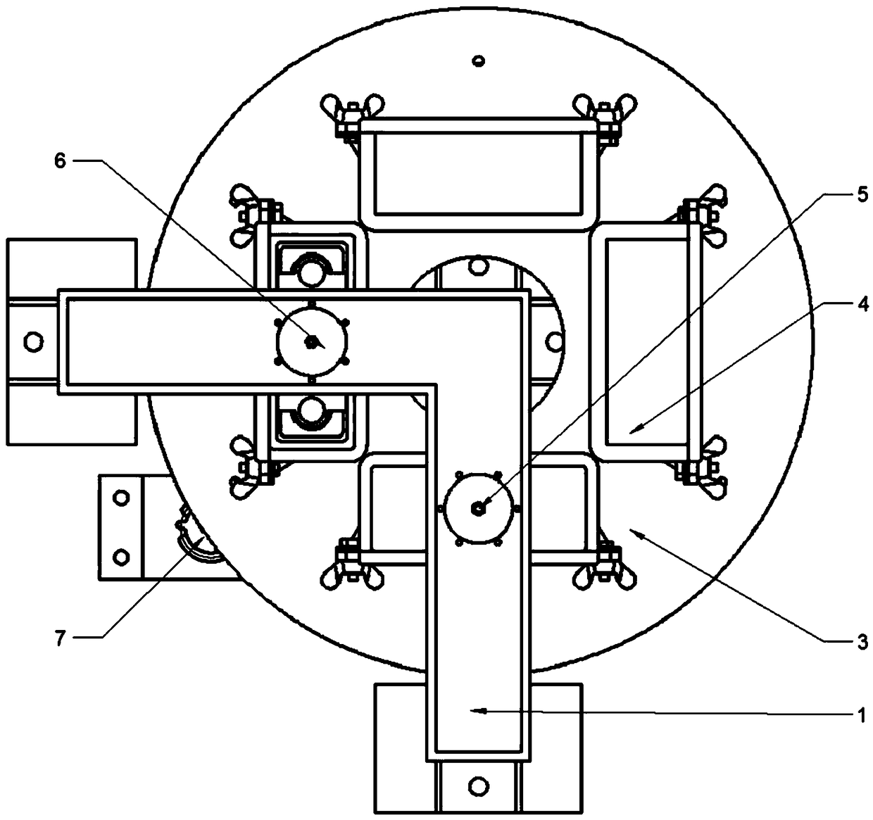
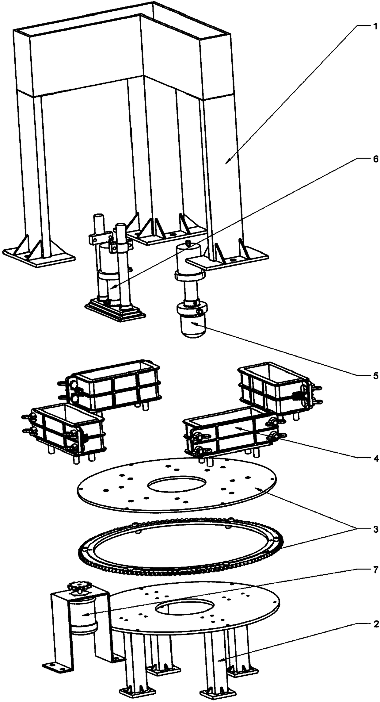
[0037] Such as Figures 1 to 11 As shown, the multi-station concrete component forming machine of the present invention includes a drive assembly 7 and a door frame 1, and the door frame 1 includes a tank box 1.3, and a vibrating assembly 5 and an extrusion assembly 6 are installed on the tank box 1.3; The bottom surface of the box 1.3 is equipped with a central column 1.2 and a side column 1.1 to form a double gantry structure. The lower ends of the central column 1.2 and the side column 1.1 are fixed on the ground or the foundation floor. The gantry structure has better stability and greater rigidity. It is not easy to deform or tilt during use, avoiding the inclination and insufficient pressure of the mold head 6.1 due to the deformation of the frame in the extrusion process, so that the concrete components are evenly stressed, and the produced concrete components have u...


PUM


Abstract

The invention relates to a concrete component forming machine, in particular to a multi-station concrete component forming machine. The multi-station concrete component forming machine comprises a driving assembly and a portal. The portal comprises a tank. A vibrating assembly and an extruding assembly are mounted on the tank, and a central stand column and side stand columns are mounted on the bottom surface of the tank, so that a double-portal structure is formed. A supporting assembly is mounted with the central stand column as the center. A rotating assembly is mounted on the supporting assembly. A die assembly is mounted on the rotating assembly. By the adoption of the multi-station concrete component forming machine, the procedures including filling, vibrating, extruding, taking and the like can be conducted at the same time, efficient continuous production can be conducted, the production efficiency is greatly improved, the structure is more stable, and both the strength and appearance of a produced concrete component can meet high requirements.

Description

technical field [0001] The invention relates to a concrete component forming machine, in particular to a multi-station concrete component forming machine. Background technique [0002] Concrete materials play an important role in the modern construction industry. In order to meet the requirements of efficiency and quality, prefabricated concrete components are required in many occasions. [0003] Most of the existing concrete component molding machines are single-station, with discontinuous production and low efficiency. [0004] And the frame of existing multi-station concrete member molding machine all adopts "T" type or "Γ" type cantilever beam structure, a plurality of molds are fixed on the bottom plate, and vibration motors are installed on the side wall or bottom plate of each mold to work First pour concrete into the mold, then start the vibrating motor to vibrate the concrete, and then the extrusion assembly is rotated to each mold with the cantilever beam driven b...

Claims


Application Information

Patent Timeline
Patent Type & Authority Patents(China)
IPC IPC(8): B28B1/093B28B3/04B28B5/08B28B13/02B28B13/04
CPCB28B1/093B28B3/04B28B5/08B28B13/02B28B13/04
Inventor 吕志杰杨鑫嵘任尧涵贾坤晗
Owner SHANDONG JIANZHU UNIV
Why Eureka
Try Eureka