
Electric locomotive cooling system

A technology for cooling systems and electric locomotives, applied in electric locomotives, locomotives, motor vehicles, etc., can solve the problems of heavy equipment weight, large space occupation, and high working noise, so as to reduce equipment weight and space occupation, and reduce equipment maintenance costs. , The effect of reducing equipment failure links

Inactive Publication Date: 2016-12-21
CRRC DALIAN CO LTD
View PDF8 Cites 4 Cited by
  • Summary
  • Abstract
  • Description
  • Claims
  • Application Information

AI Technical Summary

Problems solved by technology

These solutions generally have many problems such as large space occupation, heavy equipment weight, high working noise, low heat dissipation efficiency, many equipment failures and high maintenance costs.

Method used


Image

  • Electric locomotive cooling system

Examples


Embodiment Construction

[0009] In order to make the purpose, technical solutions and advantages of the embodiments of the present invention clearer, the technical solutions in the embodiments of the present invention will be clearly and completely described below in conjunction with the drawings in the embodiments of the present invention. Obviously, the described embodiments It is a part of embodiments of the present invention, but not all embodiments. Based on the embodiments of the present invention, all other embodiments obtained by persons of ordinary skill in the art without making creative efforts belong to the protection scope of the present invention.

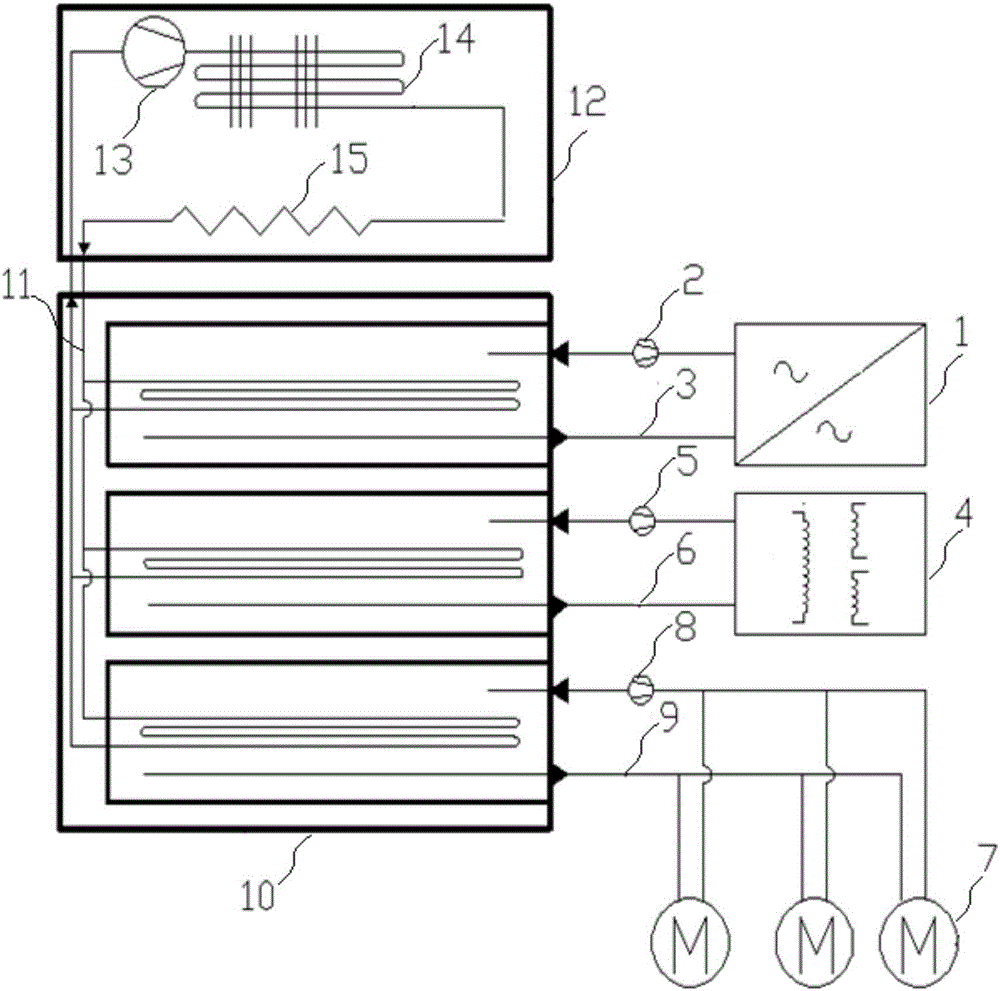
[0010] See attached figure 1 , the electric locomotive cooling system of this embodiment includes a main converter cooling water circuit 3 , a main transformer cooling oil circuit 6 , a traction motor cooling water circuit 9 , and a composite cooler 10 . Each liquid tank on the composite cooler 10 is respectively connected to the correspondi...


PUM


Abstract

The invention relates to an electric locomotive cooling system, comprising liquid medium cooling loops for cooling a main converter, a main transformer and a water-cooled traction motor respectively, and a combined cooler; liquid tanks of the combined cooler are connected respectively with the corresponding liquid medium cooling loops, a heat-absorbing line of a compression refrigerator is in S-shaped round-strip distribution in the liquid tanks of the combined cooler and is soaked in the liquid cooling medium. The radiating efficiency of the main converter, main transformer and traction motor of an electric locomotive is greatly improved, a lot of axial-flow fans are omitted, equipment weight is reduced, less space is used, fan noise is avoided, there is no stain and solid flocculent accumulation outside the combined cooler, equipment false steps are decreased, and equipment maintenance cost is reduced.

Description

technical field [0001] The invention relates to a cooling system for an electric locomotive, belonging to the technical field of railway locomotives. Background technique [0002] In the prior art, the electric locomotive adopts forced ventilation to cool the traction motor. Usually, an axial flow fan is set corresponding to several traction motors on a bogie for forced ventilation. In order to enhance the cooling effect, there is also a scheme of setting an axial flow fan corresponding to each traction motor. For the cooling of the main converter and the main transformer, the cooling circuits of the main converter and the main transformer are connected to a composite cooler, and then the composite cooler is still forced to be ventilated by an axial flow fan. These solutions generally have many problems such as large space occupation, heavy equipment weight, high working noise, low heat dissipation efficiency, many equipment failures, and high maintenance costs. Contents...

Claims


Application Information

Patent Timeline
Patent Type & Authority Applications(China)
IPC IPC(8): B61C3/00B61C17/00B60K11/02
CPCB61C3/00B60K11/02B61C17/00
Inventor 王渊博王云灏王嘉文缑智勇栾岚
Owner CRRC DALIAN CO LTD
Learn More