Near-bit constant-power wireless short transmission method and near-bit constant-power wireless short transmission device

A constant-power, near-bit technology, applied in earth-moving drilling, measurement, instruments, etc., can solve the problems of difficult machining, poor signal-to-noise ratio of received signals, complicated processing and installation, etc., and achieves easy processing and field operation. The effect of improved amplitude and signal-to-noise ratio, low maintenance costs

Active Publication Date: 2016-12-21
INST OF GEOLOGY & GEOPHYSICS CHINESE ACAD OF SCI
View PDF5 Cites 11 Cited by
  • Summary
  • Abstract
  • Description
  • Claims
  • Application Information

AI Technical Summary

Problems solved by technology

However, this implementation method also has disadvantages. The sensing signal receives different energy in different ground resistance environments. It is difficult to realize in low-resistance formations. At the same time, it is difficult to process mechanically, which is inconvenient for on-site application and high in cost.
In addition, the wireless electromagnetic short transmission method needs to install two coils on the shell. As the transmission and reception, the coils must be completely insulated from the shell. It is also obvious that the processing and installation are too complicated, the contact area with the formation and mud is small, and the transmission signal cannot be injected into the formation in a large area. In order to ensure the amplitude requirements of the received signal, the transmission power can only be increased blindly, resulting in low transmission efficiency.
At the same time, the signal-to-noise ratio of the received signal is also poor

Method used


Image

  • Near-bit constant-power wireless short transmission method and near-bit constant-power wireless short transmission device
  • Near-bit constant-power wireless short transmission method and near-bit constant-power wireless short transmission device
  • Near-bit constant-power wireless short transmission method and near-bit constant-power wireless short transmission device

Examples


Embodiment 1

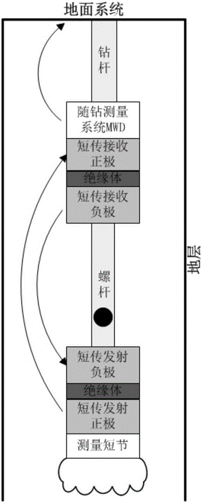
[0027] Such as figure 1 As shown, near the drill bit constant power wireless short transmission device, the device includes a transmitting part and a receiving part, the transmitting part is connected with the drill bit measurement nipple, the receiving part is connected with the measurement while drilling system, and the transmitting part connects the The measurement data of the drill bit measurement nipple is processed and shortly transmitted to the receiving unit, and the receiving unit further processes the information and sends it to the measurement-while-drilling system. An insulating short joint is inserted in the middle of the structure of the emitting part, and the insulating short joint divides the emitting part into an electrically insulated positive emitter and a negative emitter;

[0028] An insulating short joint is respectively inserted in the middle of the structure of the receiving part, and the insulating short joint divides the receiving part into an electri...


PUM


Abstract

The invention provides a near-bit constant-power wireless short transmission method and a near-bit constant-power wireless short transmission device. The device comprises a sending portion and a receiving portion, the sending portion is connected with a drill bit measurement pup joint, and the receiving portion is connected with a measurement while drilling system. The sending portion processes measurement data of the drill bit measurement pup joint and then sends to the receiving portion by short transmission, and the receiving portion further processes the data and then sends to the measurement while drilling system. An insulating pup joint is inserted into the middle of a structure of the sending portion and divides the sending portion into a sending anode and a sending cathode, and the sending anode and the sending cathode are electrically insulated. An insulating pup joint is inserted into a structure of the receiving portion and dirvides the receiving portion into a receiving anode and a receiving cathode, and the receiving anode and the receiving cathode are electrically insulated. The sending anode sends emission signals into a stratum, then the emission signals are received by the receiving anode through the stratum, a circuit is formed by addition of the receiving cathode and the sending cathode, and accordingly wireless short transmission is realized.

Description

technical field [0001] The invention mainly belongs to the field of drilling measurement, and in particular relates to a near-drill constant power wireless short transmission method and device. Background technique [0002] At this stage, near-bit logging while drilling technology is developing rapidly. Compared with conventional logging while drilling, the sensor probe of near-bit logging tools is closer to the drill bit, which can obtain drilling formation information in a timely manner and more accurately mark drilling trajectories. Reduce drilling operation risk and improve operation efficiency. Generally speaking, the near-bit LWD instrument consists of the following three parts: near-bit measurement sub, near-bit short-distance transmission device and measurement while drilling system (MWD). Among them, the near-bit measurement sub-section is arranged close to the drill bit, and accelerometers, magnetic sensors, etc. are installed inside to measure the drilling trajec...

Claims


Application Information

Patent Timeline
Patent Type & Authority Applications(China)
IPC IPC(8): E21B47/12
CPCE21B47/12E21B47/13G01V11/002H04B15/02
Inventor 孙云涛陈文轩底青云郑健杨永友张文秀
Owner INST OF GEOLOGY & GEOPHYSICS CHINESE ACAD OF SCI
Why Eureka
Try Eureka