Eureka AIR delivers breakthrough ideas for toughest innovation challenges, trusted by R&D personnel around the world.

Operating method for an exhaust gas cleaning device and corresponding drive system

An operation method and exhaust gas purification technology, which are applied in mechanical equipment, electric control of exhaust gas treatment devices, diagnostic devices of exhaust gas treatment devices, etc., can solve problems such as the contradiction of purification goals of exhaust gas catalytic converters, and achieve the goal of improving the purification effect Effect

Active Publication Date: 2016-12-21
MAN NUTZFAHRZEUGE AG
View PDF6 Cites 0 Cited by
  • Summary
  • Abstract
  • Description
  • Claims
  • Application Information

AI Technical Summary

Problems solved by technology

[0003] A disadvantage of such known methods is the fact that engine-side measures for improving the cleaning action of the exhaust gas catalytic converter (for example ignition angle retardation adjustment) lead to more fuel consumption and a correspondingly increased CO 2 emission
That is to say, for such known methods there is optimization of the cleaning effect of the exhaust gas catalytic converter on the one hand and the fuel consumption and CO on the other hand. 2 Contradictions between the objectives of the minimization of emissions

Method used


Image

  • Operating method for an exhaust gas cleaning device and corresponding drive system
  • Operating method for an exhaust gas cleaning device and corresponding drive system
  • Operating method for an exhaust gas cleaning device and corresponding drive system

Examples


Embodiment Construction

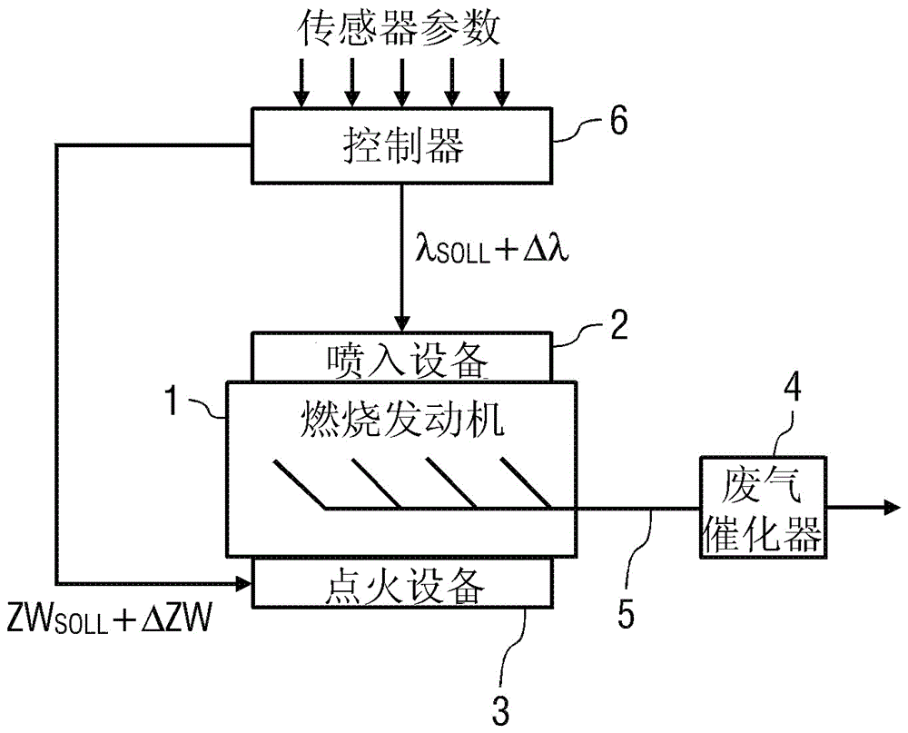
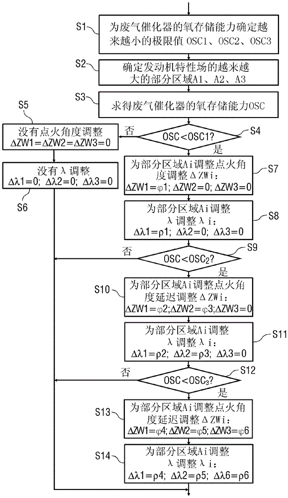
[0040] Figure 1A A flow chart is shown for explaining a part of the operating method according to the invention, which part is operated only once during a driving cycle, that is to say on the one hand with the ignition switched on and the engine started and on the other hand with the ignition switched off and the engine between stops.

[0041] In the first step S1, the oxygen storage capacity of the exhaust gas catalytic converter (OSC: O xygen S storage C apacity) to determine smaller and smaller limit values ​​OSC1, OSC2, . . . , OSCn. Apply OSC1>OSC2>…>OSCn.

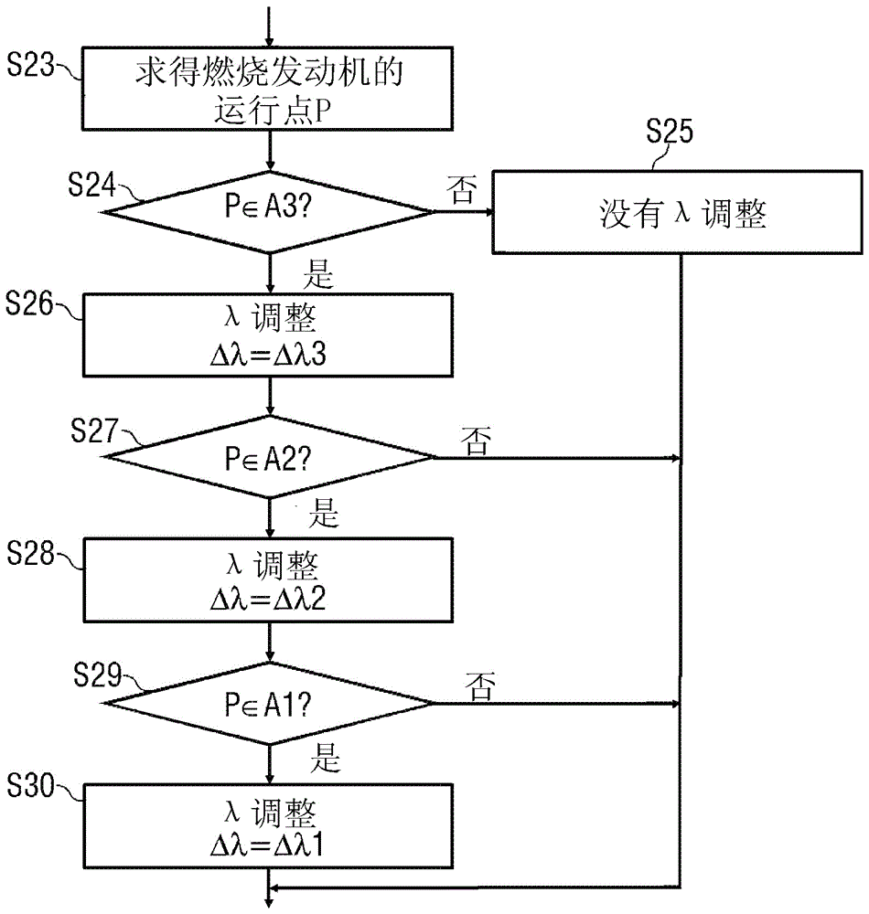
[0042] In a further step S2, increasingly larger partial areas A1, A2, . . . figure 2 is schematically shown in . For some areas A1, A2,...An, A1

[0043] The following description and figures show an example of a system with three subranges and three OSC limit values.

[0044] In step S3 , the real-time value OSC of the oxygen storage capacity of the exhaust gas catalytic converter is subs...


PUM


Abstract

The invention relates to an operating method for an exhaust gas cleaning device and a corresponding drive system. The device comprises an exhaust gas catalytic converter (4). The method comprises the following steps: determining a catalyst characteristic parameter of the exhaust gas catalytic converter (4), wherein the catalyst characteristic parameter representing the cleaning effect of the exhaust gas catalytic converter (4); taking a measure for improving the cleaning effect of the exhaust gas catalytic converter (4) when the catalytic converter parameter indicates an insufficient cleaning effect of the exhaust gas catalytic converter (4); and determining an operating point of an internal combustion engine (1) in a motor field. The invention provides for the motor measure to be initiated to improve the cleaning effect of the exhaust gas catalytic converter (4) as a function of the operating point of the internal combustion engine (1). Furthermore, the invention comprises a corresponding drive system.

Description

technical field [0001] The invention relates to an operating method for an exhaust gas purification system having an exhaust gas catalytic converter, for example a three-way catalytic converter, for purifying exhaust gas on a combustion engine, in particular in a motor vehicle. Furthermore, the invention relates to a drive system, in particular for a motor vehicle with a combustion engine and an exhaust gas catalytic converter. Background technique [0002] Exhaust gas purification systems are known from the prior art for the purification of exhaust gases on combustion engines, which use three-way catalytic converters. However, such three-way catalytic converters are subject to aging caused by natural and environmental influences, as a result of which the so-called light-off temperature increases, from which the exhaust gas catalytic converter is effective and provides a sufficient cleaning effect. In combustion engines with relatively low exhaust gas temperatures, there is...

Claims


Application Information

Patent Timeline
IPC IPC(8): F01N9/00F01N11/00F02D43/00
CPCF01N9/00F01N11/00F02D37/02F01N2430/08F01N2430/04F01N3/101F02D41/0235F02D41/024F01N2900/0416F01N2900/08F01N2900/1602F01N2900/1624F02D2200/0802F02D2200/0816F02D41/1456F02D41/2451F02D2200/0814Y02A50/20Y02T10/12Y02T10/40F01N3/20
Inventor F.W.普吕姆
Owner MAN NUTZFAHRZEUGE AG
Why Eureka
Eureka Blog
Learn More