Metal smelting waste slag high-temperature waste heat generation device

A technology of metal smelting and waste heat power generation, which is applied in the field of mechanical equipment, can solve the problems of low utilization rate, excessive metal consumption, and low utilization rate of waste slag and waste heat, and achieve the effect of reducing labor intensity and improving utilization rate

Active Publication Date: 2016-12-21
兴和县新太铁合金有限公司
View PDF8 Cites 0 Cited by
  • Summary
  • Abstract
  • Description
  • Claims
  • Application Information

AI Technical Summary

Problems solved by technology

It uses the excess heat energy on the waste slag produced after metal smelting as a heat source to produce steam for power generation. Because the temperature of the working medium is not high, the boiler is large in size and consumes a lot of metal. In the prior art, the waste slag is transferred from the smelting furnace In the process of reaching the steam boiler, the waste heat on the waste slag will dissipate, resulting in a lower utilization rate. The existing steam boilers are equipped with water storage devices inside and waste slag outside. This structure does not have a high utilization rate of waste heat from waste slag.

Method used


Image

  • Metal smelting waste slag high-temperature waste heat generation device
  • Metal smelting waste slag high-temperature waste heat generation device
  • Metal smelting waste slag high-temperature waste heat generation device

Examples


specific Embodiment approach

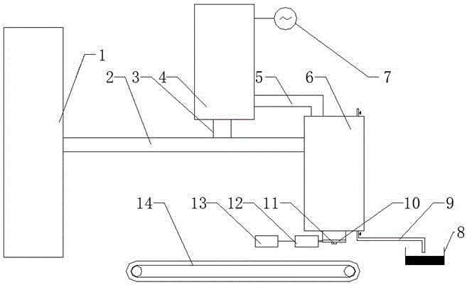
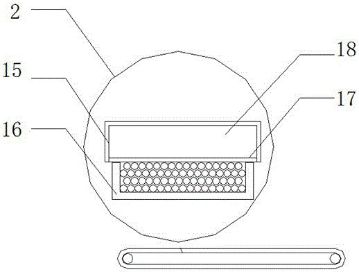
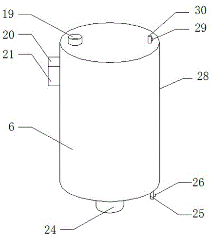
[0017] Specific implementation method: the waste slag from the metal smelting furnace 1 enters the conveying device 2 and is sent to the steam boiler 1. The waste slag follows the heat emitted during the movement of the adiabatic conveying tank 16 and enters the water holding chamber 18 through the heat conducting plate 17 for heating. The water in the water chamber 18 generates water vapor, which is then transported to the steam turbine 4 through the steam pipe-3. This process improves the waste heat utilization rate. The waste residue enters the waste residue inlet 21 through the conveying device 2, and then enters the waste residue storage chamber 23. The waste residue is placed in the waste residue chamber. The heat dissipated in the waste residue storage chamber 23 enters the water supply chamber 22 through the heat conduction plate 26, heats the water in the water supply chamber 22 to generate water vapor, and then transports it to the steam turbine 4 through the steam tra...


PUM


Abstract

The invention provides a metal smelting waste slag high-temperature waste heat generation device. The metal smelting waste slag high-temperature waste heat generation device comprises a steam structure, a generation device structure, a metal smelting waste slag conveying structure and a metal smelting furnace. A heat conduction plate I is installed at the upper end of a heat-insulation conveying groove. A water containing cavity is formed in the upper end of the heat conduction plate I. A heat-insulation outer shell I is installed at the upper end of the water containing cavity. A heat-insulation outer shell II is installed at the lower end of a steam outlet. A water inlet is assembled on the right side of the steam outlet. A control valve II is arranged on the water inlet. A water flowing opening is installed on the left side of the heat-insulation outer shell II. A waste slag inlet is assembled under the water flowing opening. A water adding cavity is arranged at the right end of the water flowing opening. A heat conduction plate II is installed inside the water adding cavity and internally provided with a waste slag containing cavity. A waste slag outlet is assembled at the lower end of the waste slag containing cavity. A water outlet is installed on the right side of the waste slag outlet. A control valve II is arranged on the water outlet. The metal smelting waste slag high-temperature waste heat generation device improves the waste heat utilization rate, can recycle water resources and relieves labor intensity.

Description

technical field [0001] The invention relates to a high-temperature waste heat power generation device for metal smelting waste residue, which belongs to the field of mechanical equipment. Background technique [0002] In the current metal smelting process, most of them use the technology of converting the excess heat energy on the waste slag generated after metal smelting into electrical energy. Waste heat power generation is not only energy-saving, but also conducive to environmental protection. The important equipment for waste heat power generation is the steam boiler. It uses the excess heat energy on the waste slag produced after metal smelting as a heat source to produce steam for power generation. Because the temperature of the working medium is not high, the boiler is large in size and consumes a lot of metal. In the prior art, the waste slag is transferred from the smelting furnace In the process of reaching the steam boiler, the waste heat on the waste slag will...

Claims


Application Information

Patent Timeline
Patent Type & Authority Applications(China)
IPC IPC(8): F22B1/04F27D17/00F23J1/02F27D3/15F27D19/00F01K11/00F01D15/10
CPCF01D15/10F01K11/00F22B1/04F23J1/02F27D3/1545F27D17/004F27D19/00F27D2017/006Y02P10/25
Inventor 李朋国刘苗李浪
Owner 兴和县新太铁合金有限公司
Why Eureka
Try Eureka