Gas converting method and system

A gas conversion and gas technology, applied in the field of gas conversion methods and systems, can solve the problems of restricting the application of liquefied gas, unfavorable sustainable economic development of the liquefaction industry, and large energy consumption, so as to improve energy utilization, improve liquefaction efficiency, and save energy. cost effect

Active Publication Date: 2016-12-21
陈正洪
View PDF6 Cites 4 Cited by
  • Summary
  • Abstract
  • Description
  • Claims
  • Application Information

AI Technical Summary

Problems solved by technology

[0003] However, gas liquefaction requires a large amount of energy, which limits the application of liquid gas and is not conducive to the sustainable economic development of the liquefaction industry.

Method used


Image

  • Gas converting method and system
  • Gas converting method and system
  • Gas converting method and system

Examples


Embodiment 1

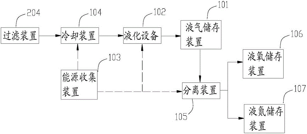
[0058] Such as figure 1 As shown, in the first embodiment, the gas conversion system of the present invention can also include a separation device 105, which can be communicated with the liquid gas outlet of the liquefaction device 102, and the outlet is communicated with the liquid gas storage device 101, and then the The substances to be separated are introduced into the separation device 105, from which liquid nitrogen and liquid oxygen are separated; meanwhile, the separation device 105 is also provided with a liquid oxygen outlet and a liquid nitrogen outlet for outputting liquid nitrogen and liquid oxygen.

[0059] In order to realize the separate storage of liquid nitrogen and liquid oxygen, a liquid oxygen storage device 106 and a liquid nitrogen storage device 107 can also be provided, wherein the liquid oxygen storage device 106 is connected with the liquid oxygen outlet of the separation device 105, and the liquid nitrogen storage device 107 is connected with the sep...

Embodiment 2

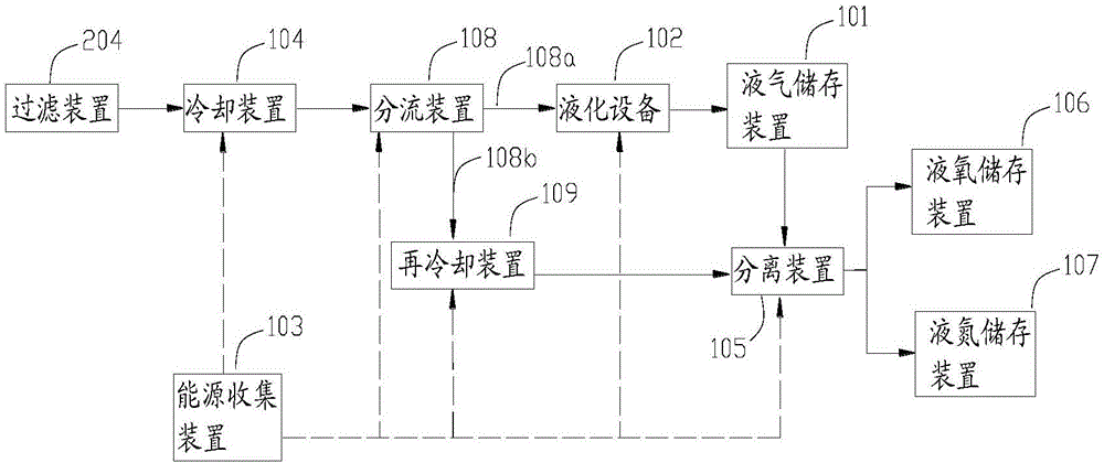
[0070] Such as figure 2 As shown, in the second embodiment, the liquefaction equipment 102 is a cryogenic device. Specifically, the separation device 105 can also be integrated with the cryogenic device, so as to separate liquid oxygen and liquid nitrogen while liquefying low-temperature air, that is At this time, the liquefaction equipment 102 is a cryogenic device with a separation function, which can directly liquefy and separate liquid oxygen and liquid nitrogen.

[0071] Compared with Embodiment 1, this embodiment can directly separate liquid oxygen and liquid nitrogen during liquefaction, which improves efficiency, and does not require a liquid-gas storage device 101, which reduces costs and saves storage space.

[0072] Specifically, the temperature of the cryogenic device can be controlled to achieve liquefaction of air. During the liquefaction process, the difference in liquefaction temperature of oxygen and nitrogen can be used to separate liquid oxygen and liquid n...

Embodiment 3

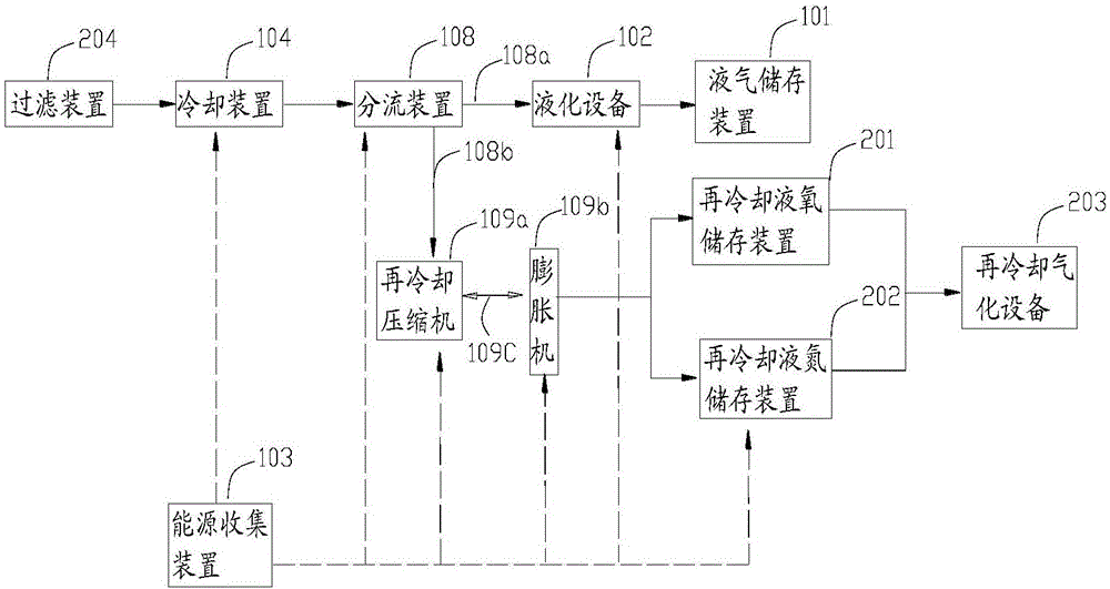
[0076] Such as image 3 As shown, in the third embodiment, a circulation air channel 109c can be provided between the expander 109b and the recooling compressor 109a to recool the low-temperature air circulation, and part of the liquid oxygen and part of liquid nitrogen; the recooling device 109 can be respectively provided with an output port for outputting liquid oxygen and an output port for outputting liquid nitrogen, and then the liquid oxygen and liquid nitrogen obtained by recooling are transported to the re-cooling system respectively through the delivery pipeline. The liquid oxygen storage device 201 is cooled and the liquid nitrogen storage device 202 is subcooled.

[0077] At the same time, the present invention may also include a subcooling gasification device 203 communicated with at least one of the subcooling liquid oxygen storage device 201 and the subcooling liquid nitrogen storage device 202, for recooling the obtained liquid oxygen and / or The liquid nitroge...


PUM


Abstract

The invention provides a gas converting method and system capable of storing and converting clean energy and improving the liquefying benefits. The gas converting system comprises a liquid gas storage device and a liquefying device. The liquefying device is provided with an air inlet and a liquid gas outlet. The liquid gas outlet communicates with the liquid gas storage device. The gas converting system further comprises an energy collecting device and a cooling device, wherein the energy collecting device is used for collecting pushing energy, the cooling device communicates with an air source, compression and stepped cooling are conducted on air through the pushing energy, low-temperature air is formed, and a low-temperature air outlet is formed. The liquefying device is used for liquefying the low-temperature air through the pushing energy, so that liquid air is manufactured and output through the liquid gas outlet, high-pressure gas obtained after liquid gas gasification is used for conducting power generation and / or external acting, and cold energy generated through gasification is recycled. The gas converting method comprises the steps that the energy is collected to conduct compression and stepped cooling on the air, the low-temperature air is formed and further liquefied, liquid air is manufactured, and the high-pressure gas obtained after liquid gas gasification is used for conducting power generation and / or external acting.

Description

technical field [0001] The invention relates to the technical field of gas liquefaction, in particular to a gas conversion method and system. Background technique [0002] Liquefied gas is a physical process of converting gas into a liquid state. Liquefied gas has great commercial and medical value and is an important energy storage carrier. In recent years, the gas liquefaction industry has developed vigorously. [0003] However, gas liquefaction requires a large amount of energy, which limits the application of liquid gas and is not conducive to the sustainable economic development of the liquefaction industry. [0004] Therefore, how to design a gas conversion method and system so as to improve the efficiency of liquefaction and energy conversion while improving the economical efficiency of liquefaction has become a technical problem urgently to be solved by those skilled in the art. Contents of the invention [0005] The purpose of the present invention is to provide...

Claims


Application Information

Patent Timeline
IPC IPC(8): F25J1/02F25J3/04
CPCF25J1/0234F25J3/04636F25J2205/84F25J2210/40F25J1/0012F25J1/0045F25J1/0251F25J3/04496F25J3/04509F25J2260/30
Inventor 陈正洪杨桂芳
Owner 陈正洪
Why Eureka
Try Eureka