Triggering type probe calibration method of coordinate measuring machine

A technology of coordinate measuring machine and calibration method, which is applied in the direction of point coordinate measurement and electromagnetic measuring device, can solve the problems of unfavorable measurement results, non-negligible influence, difference between distance and nominal distance, etc., so as to improve calibration accuracy and ensure measurement The effect of precision

Active Publication Date: 2016-12-21
HEFEI UNIV OF TECH
View PDF6 Cites 13 Cited by
  • Summary
  • Abstract
  • Description
  • Claims
  • Application Information

AI Technical Summary

Problems solved by technology

[0005] In the above calculation, the nominal distance between the origin of the probe coordinate system and the center of the small ball at the end of the measuring rod is actually used, but the screw connection is used between the measuring rod and the probe sensor, and the origin of the probe coordinate system to The actual distance between the center of the small ball at the end of the measuring rod cannot be consistent with the nominal distance; at the same time, when different operators install, due to different forces, the distance between the origin of the coordinate system of the measuring head and the center of the small ball at the end of the measuring rod will be different. The difference between the distance and the nominal distance is different
Therefore, it is impossible to accurately obtain the position of the center of the standard ball theoretically by using the existing method, which is not conducive to ensuring the accuracy of the measurement results, especially when the rotatable measuring head is used and the measuring head needs to be rotated to different directions during the measurement process. This effect cannot be ignored when measuring

Method used


Image

  • Triggering type probe calibration method of coordinate measuring machine
  • Triggering type probe calibration method of coordinate measuring machine
  • Triggering type probe calibration method of coordinate measuring machine

Examples


Embodiment Construction

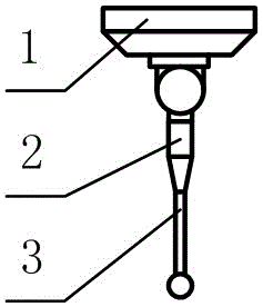
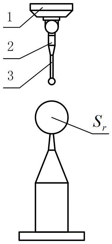
[0032] The present invention is described in further detail now in conjunction with accompanying drawing. All the accompanying drawings are simplified schematic diagrams, which only illustrate the basic method of the present invention in a schematic manner, so they only show the schematic diagrams of the touch probe, standard ball and measured spherical surface related to the present invention. A coordinate measuring machine trigger probe calibration method, including the coordinate measuring machine used probe and standard ball S r , the measuring head is mainly composed of a rotatable measuring seat 1, a measuring head sensor 2 and a measuring rod 3; it is characterized in that it is carried out according to the following steps:

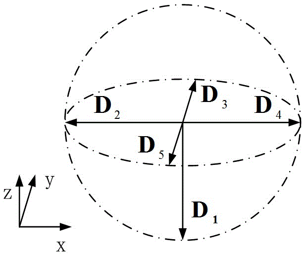
[0033] 1.1. Place standard ball S r Fixed, rotate the probe to four or more different directions D1 、D 2 ,...,D n (n≥4), under the condition of no probe compensation, that is, no compensation for the radius of the small ball at the end of the me...


PUM


Abstract

The invention discloses a triggering type probe calibration method of a coordinate measuring machine. According to the method, a probe is rotated to four or more different directions, a standard ball is measured under different probe compensation conditions, four or more measured spherical centers are used to construct a sphere in a least square method, the center of the constructed sphere serves as the center of the standard ball, and a theoretical value of the radius of the sphere equals the distance from an origin point of a probe coordinate system to the spherical center of a small ball in the end portion of a measuring rod. Thus, triggering type probe calibration can be completed via simple calculation. The probe calibration method is suitable for triggering type problems, using rotatable measuring seats, commonly used in the orthogonal coordinate measuring machine.

Description

technical field [0001] The invention relates to the field of coordinate measurement technology and equipment in geometric quantity measurement, in particular to a calibration method for a trigger type probe of a coordinate measuring machine. Background technique [0002] Coordinate Measuring Machine (CMM for short) is the most representative general-purpose digital geometric quantity measuring instrument. When using a coordinate measuring machine, the probe is moved to the desired position by moving the moving parts of the coordinate measuring machine, and the coordinate values ​​of the measured points on the surface of the workpiece to be measured are collected. The error analysis or model reconstruction of the measured workpiece is realized through software processing and analysis of the collected coordinate values ​​of the measured points. Coordinate Measuring Machines are often referred to as Orthogonal Coordinate Measuring Machines. [0003] The trigger probe is the m...

Claims


Application Information

Patent Timeline
Patent Type & Authority Applications(China)
IPC IPC(8): G01B7/016
CPCG01B7/016
Inventor 李维诗赵岩岩王雨于连栋夏豪杰
Owner HEFEI UNIV OF TECH
Why Eureka
Try Eureka