Eureka AIR delivers breakthrough ideas for toughest innovation challenges, trusted by R&D personnel around the world.

Manufacturing method for electromagnetic wave structure stealth

A manufacturing method and electromagnetic wave technology, applied to chemical instruments and methods, pharmaceutical equipment, electrical digital data processing, etc., can solve problems such as poor stealth effect, mismatched surface impedance, large cumulative error, etc., and achieve improved combat penetration Ability and survivability, good surface impedance matching, effect of improved absorbing efficiency

Active Publication Date: 2016-12-21
XI AN JIAOTONG UNIV
View PDF2 Cites 14 Cited by
  • Summary
  • Abstract
  • Description
  • Claims
  • Application Information

AI Technical Summary

Problems solved by technology

[0005] The above two methods can produce a broadband stealth structure with certain mechanical properties, but there are still some common deficiencies
1. The above methods have two problems in terms of stealth performance: there is a certain degree of surface impedance mismatch between the outermost wave-transparent material and the external environment, and there are more reflected waves at the interface between the two, which affects the stealth effect ; When the electromagnetic wave is incident at a large angle, the electromagnetic wave absorption rate is low, the reflectivity is high, and the stealth effect is not good
2. The above methods are difficult to realize the integrated manufacturing of invisible structures
The process is cumbersome, the processing cycle is long, the cumulative error is large, and the integrated manufacturing of the structure cannot be realized.
3. The structural complexity that can be achieved by the above methods is low, and it is difficult to realize complex stealth structures with aerodynamic functions such as surface microstructures and complex air inlets, and cannot be used for the manufacture of highly aerodynamic stealth structures

Method used


Image

  • Manufacturing method for electromagnetic wave structure stealth
  • Manufacturing method for electromagnetic wave structure stealth
  • Manufacturing method for electromagnetic wave structure stealth

Examples


Embodiment Construction

[0026] The present invention will be described in further detail below in conjunction with the accompanying drawings and embodiments, taking X-band horizontal wing part plane stealth structure manufacturing as an embodiment.

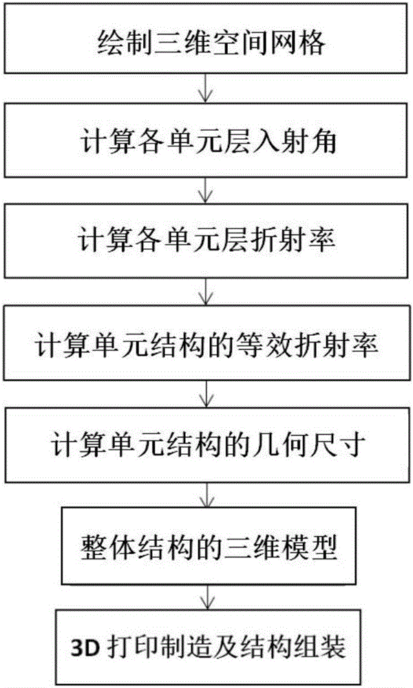
[0027] refer to figure 1 , a method for manufacturing an electromagnetic wave structure invisible, comprising the following steps:

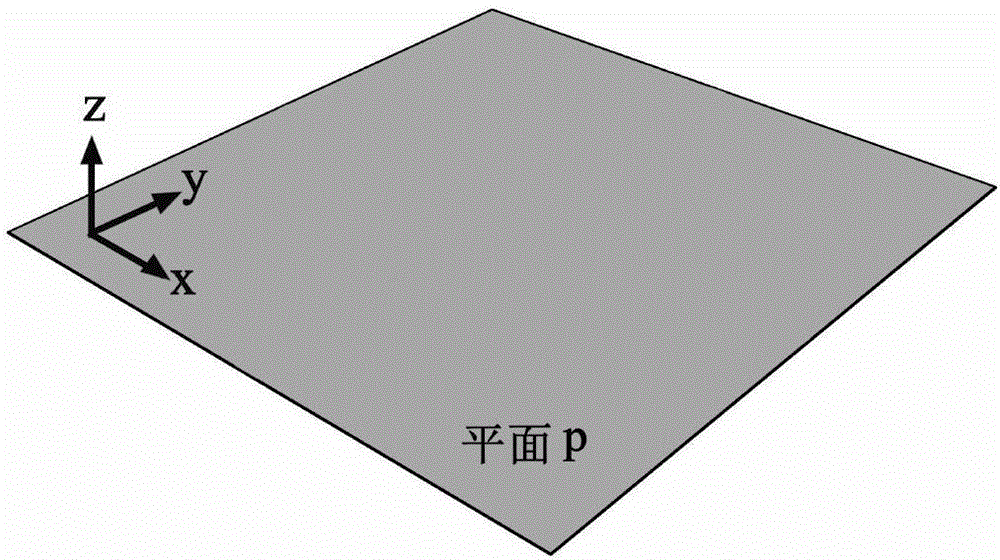
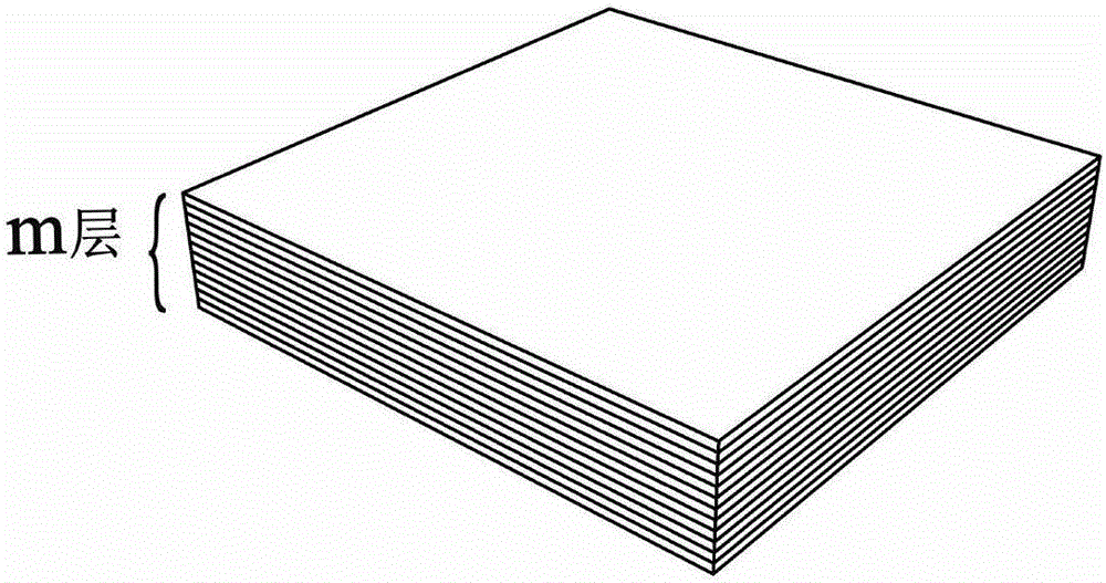
[0028] 1) Refer to figure 2 , image 3 , Figure 4 and Figure 5 , according to the shape of the stealth target, the unit layer grid division and the unit structure grid division are completed, and a three-dimensional space grid composed of several cube unit grids is obtained; the x band is selected as the stealth band, and the minimum wavelength λ in this band is 25mm, a is the side length of the cube unit grid, a satisfies a≤1 / 4λ, take a=5mm; m is the number of layers of the unit layer, m≥12, take m=12; select the aircraft horizontal wing surface 300mm×300mm The square plane area is the target object to be hidden. I...


PUM


Abstract

The invention relates to a manufacturing method for electromagnetic wave structure stealth. Firstly, according to the shape of a stealth target, unit layer grid division and unit structure grid division are completed, so that a three-dimensional spatial lattice composed of a plurality of square unit lattices is obtained; then, an electromagnetic wave propagation path is planned in the three-dimensional spatial lattice; electromagnetic wave incidence angles of various unit layers are calculated; refractive indexes of various unit layers are calculated; then, equivalent dielectric constants of unit structures in various unit layers are calculated; geometrical dimensions of the unit structures are calculated; a woodpile structure is used as a unit structure of each unit layer; then, a three-dimensional model of the unit structures is established according to the column width of the woodpile structure in each unit layer; and finally, 3D printing and manufacturing and structural assembling are carried out. By means of the manufacturing method disclosed by the invention, the stealth effect is improved; integrated manufacturing of the structure is realized; and the manufacturing method can be used for manufacturing a high-pneumatic stealth structure.

Description

technical field [0001] The invention relates to the technical field of electromagnetic wave structure invisibility, in particular to a manufacturing method for electromagnetic wave structure invisibility. Background technique [0002] Structural stealth has become a research hotspot in the field of stealth technology in recent years. Structural stealth refers to the specific arrangement of materials according to the stealth function requirements to form a structure with electromagnetic wave stealth function, so as to achieve the purpose of stealth. The stealth effect depends on the structure rather than the material. itself, thus called structural invisibility. The existing structural invisibility is mainly the invisibility of the laminated plate structure and the invisibility of the honeycomb sandwich structure. [0003] Invisible manufacturing method of laminated board structure: Calculate the electromagnetic parameters and thickness of each layer of material according to...

Claims


Application Information

Patent Timeline
IPC IPC(8): G06F17/50G06T17/20B29C67/00B33Y10/00B32B15/06B32B15/20B32B25/08B32B37/12
CPCG06T17/20B32B15/06B32B15/20B32B25/08B32B37/1284B33Y10/00B32B2307/412B32B2307/208B32B2605/16B32B2605/18B32B2605/12B32B2535/00G06F30/18G06F30/23
Inventor 田小永尹丽仙
Owner XI AN JIAOTONG UNIV
Why Eureka
Eureka Blog
Learn More