Low-voltage universal circuit breaker interrupter

A universal circuit breaker technology, applied in the direction of circuits, electrical components, electric switches, etc., can solve the problems of small effective area of ​​arc extinguishing grids, affecting the breaking performance of circuit breakers, affecting the absorption of arc heat, etc., to improve the cooling effect, Simple structure and good economical effect

Active Publication Date: 2018-10-02
JIANGSU LUOKAI MECHANICAL & ELECTRICAL
View PDF5 Cites 1 Cited by
  • Summary
  • Abstract
  • Description
  • Claims
  • Application Information

AI Technical Summary

Problems solved by technology

Its disadvantages are as follows: First, the structure has the risk of poor exhaust. When the high-temperature ionized gas cannot be discharged in time and effectively, it will affect the smooth entry of the arc into the arc extinguishing grid, and it is easy to cause arc back breakdown, which increases the The arcing time affects the breaking performance of the circuit breaker
Fourth, the arc extinguishing grid of the existing arc extinguishing chamber is provided with an arc-shaped groove corresponding to the central axis on its upper part, and the arc-shaped groove passes through the inclined surface to the bottom to form a symmetrical oblique foot, and the effective area of ​​the arc-extinguishing grid is relatively small. Small, affects the absorption of arc heat, so it is not good for arc extinguishing

Method used


Image

  • Low-voltage universal circuit breaker interrupter
  • Low-voltage universal circuit breaker interrupter
  • Low-voltage universal circuit breaker interrupter

Examples


Embodiment Construction

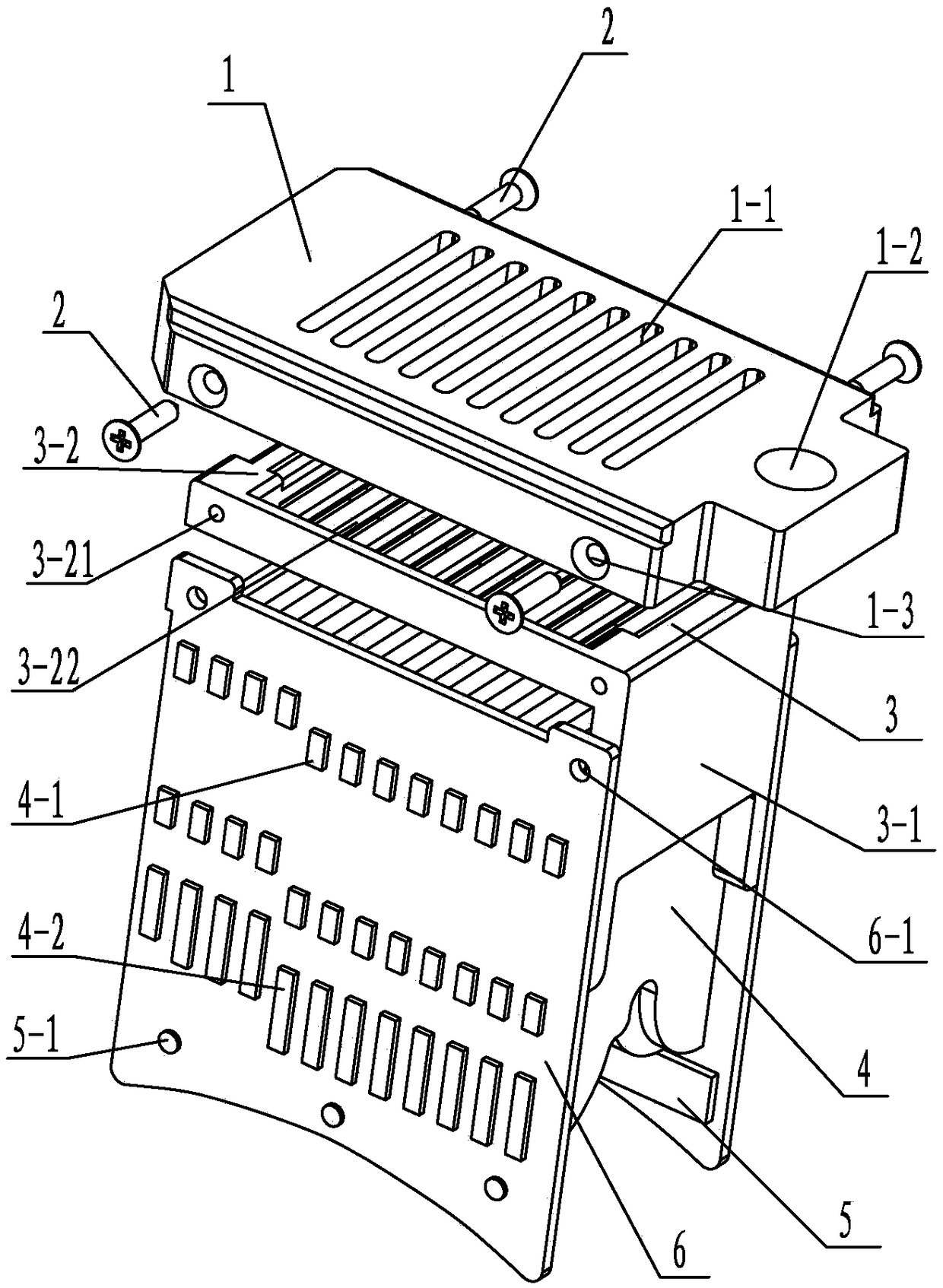
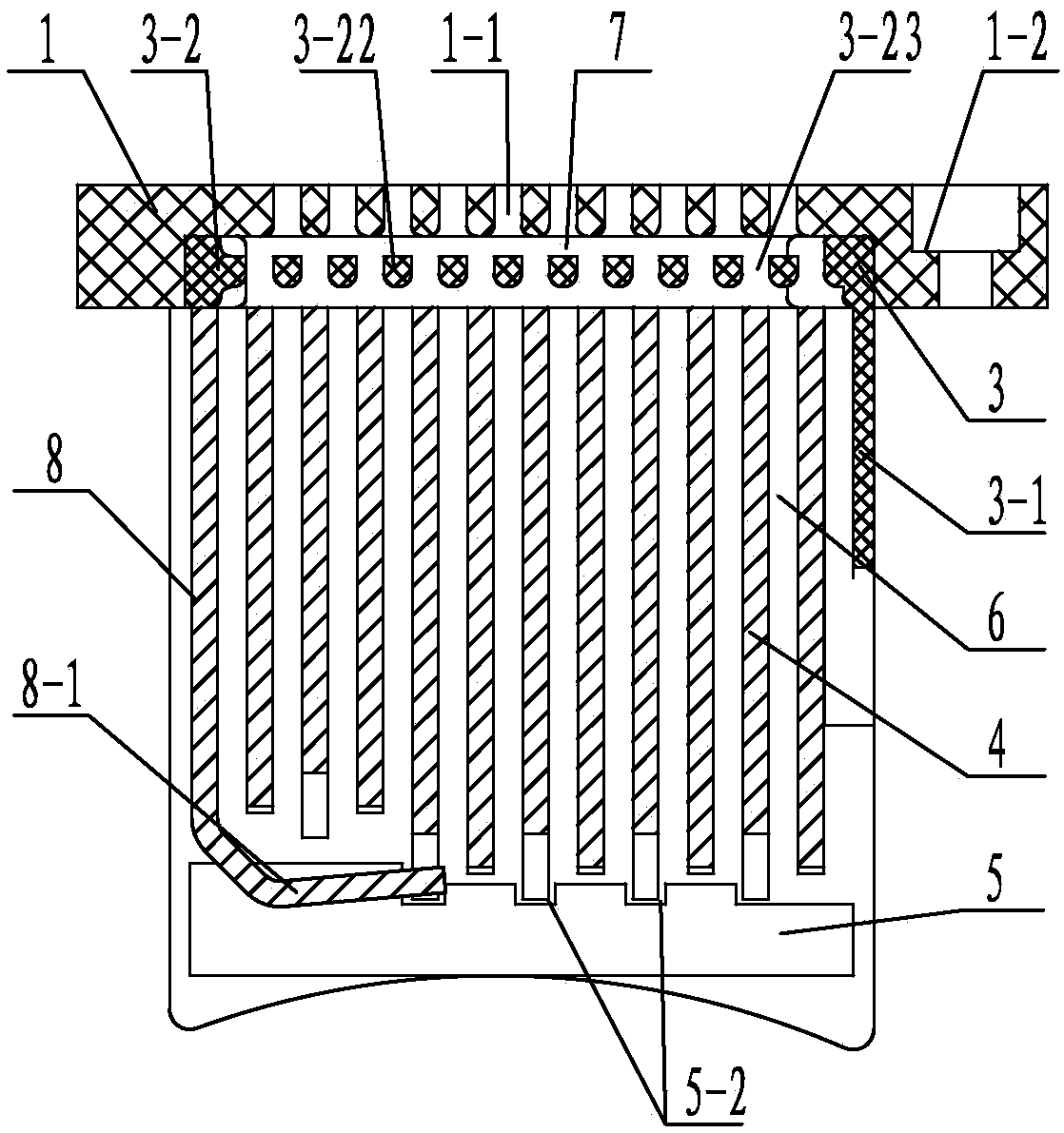
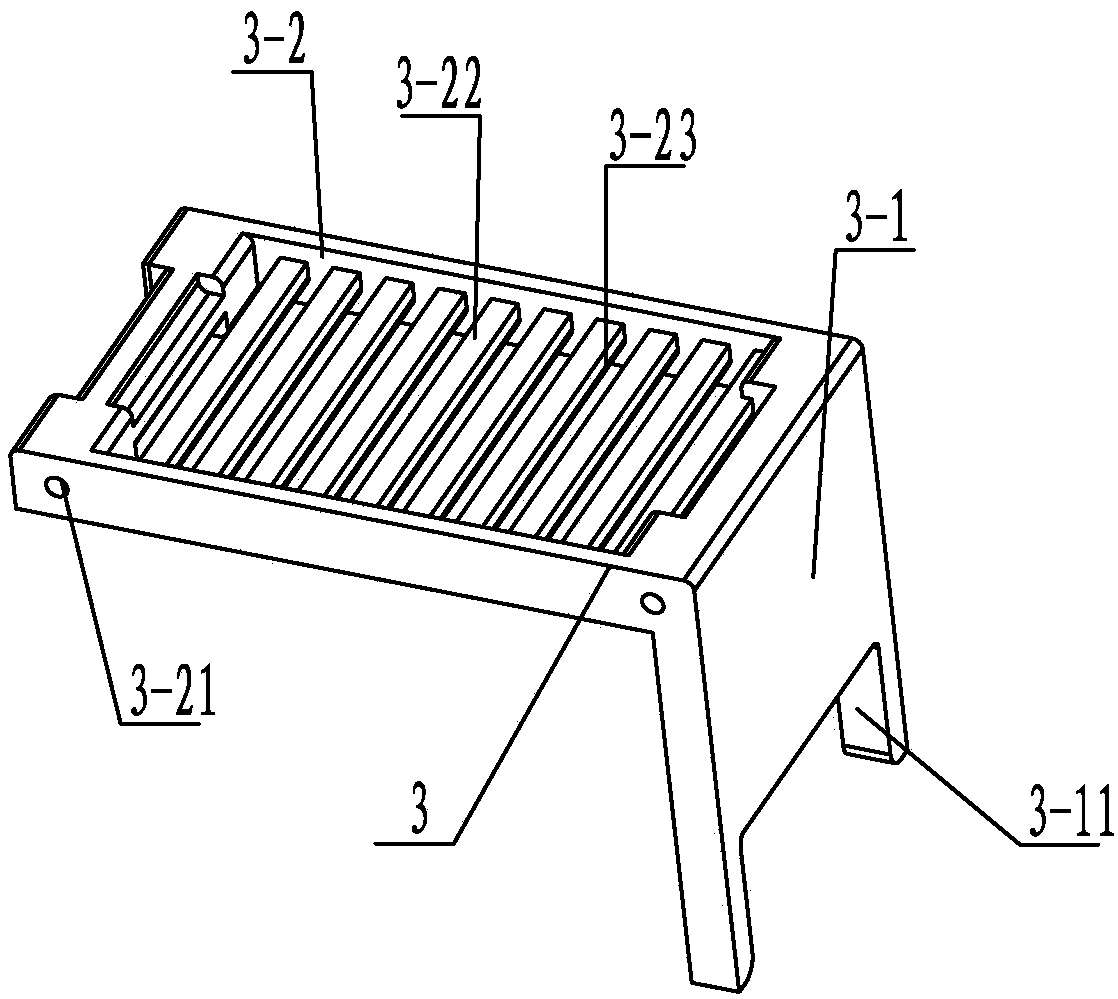
[0023] See Figure 1~5 As shown, the arc extinguishing chamber of the low-voltage universal circuit breaker of the present invention includes a cover plate 1 and an arc extinguishing grid 4 assembly. See figure 1 , 2 As shown, the cover plate 1 made of molding compound of the present invention is provided with a plurality of upper exhaust slots 1-1 parallel to and spaced apart from the arc extinguishing grid sheet 4, and the upper exhaust slots 1-1 are two The end is arc-shaped, and the arc-extinguishing fence 3 is installed in the concave installation groove at the bottom of the cover plate 1, see Figure 1~3 As shown, the arc extinguishing grid 3 made of molding compound in the present invention includes a square-shaped upper frame 3-2 and side baffles 3-1, and the upper frame 3-2 is provided with arc extinguishing grids 4 parallel to and spaced from A plurality of grid bars 3-22 are set, the lower exhaust slots 3-23 between two adjacent grid bars 3-22 are arranged alter...


PUM


Abstract

The invention relates to a low-voltage universal-type circuit breaker arc extinguishing chamber. An arc extinguishing barrier is arranged at the lower part of a cover plate; multiple lower air vent holes in the upper frame of the arc extinguishing barrier and multiple upper air vent holes in the cover plate are arranged in an interleaved mode; the cavity between the upper part of each grid bar of the upper frame and the lower part of the cover plate forms an upper air exhaust layer; an arc extinguishing grid plate assembly comprises gas producing pieces connected onto two arc insulating wall plates, an L-shaped arc striking plate and multiple arc extinguishing grid plates; each arc extinguishing grid plate is provided with an upper arc groove with a downward notch and arc surfaces smoothly transiting to the bottom part externally and convexly to two sides; the curvature radius of the arc groove off the center is 2.5 to 3.5 mm; the distance between the groove top of the upper arc groove and the top of the arc extinguishing grid plate is 2 / 3 to 3 / 4 the total height of the arc extinguishing grid plate; the arc surfaces at two sides of each arc extinguishing grid plate form a long arc pin and a short arc pin with a height difference; and the long arc pins and the short arc pins on two adjacent arc extinguishing grid plates are arranged in an interleaved mode. The low-voltage universal-type circuit breaker arc extinguishing chamber has the advantages that the structure is simple; the arc extinguishing effects are good; the limit breaking capacity can be improved; and the manufacturing cost is low.

Description

technical field [0001] The invention relates to an arc extinguishing chamber of a low-voltage universal circuit breaker, which belongs to the technical field of thin steel grid plate arc extinguishing chambers. Background technique [0002] During the breaking process of the circuit breaker, the dynamic and static contacts of the contact system are opened instantly, and an arc is generated. The arc has the following hazards: (1) Although the contact is opened, the circuit to be cut off is not actually disconnected due to the existence of the arc; (2) When the short-circuit current is broken, the arc temperature can reach 7000K ~ 20000K, which is enough Melt the contacts and destroy the circuit breaker; (3) The high-temperature ionized gas generated by the arc heats the surrounding objects and causes a fire. [0003] The arc extinguishing chamber of the low-voltage universal circuit breaker is set up for extinguishing the arc. According to the principle of short-arc arc ext...

Claims


Application Information

Patent Timeline
Patent Type & Authority Patents(China)
IPC IPC(8): H01H9/34
CPCH01H9/342
Inventor 倪文元宋伯鑫翟文闯
Owner JIANGSU LUOKAI MECHANICAL & ELECTRICAL
Why Eureka
Try Eureka