Broadband three-wave-beam array antenna

An array antenna and beam technology is applied in the field of broadband three-beam array antennas to achieve good side lobe and grating lobe suppression performance, improve network capacity, and reduce adjacent area interference.

Active Publication Date: 2016-12-21
GUANGDONG BROADRADIO COMM TECH
View PDF6 Cites 15 Cited by
  • Summary
  • Abstract
  • Description
  • Claims
  • Application Information

AI Technical Summary

Problems solved by technology

Although the number of beams is increased to 3, the working frequency band can only cover 1710-2170MHz
The existing three-beam technology, if the frequency band is widened to the 1700-2700MHz frequency band, will produce very high horizontal grating lobes at the frequency of 2700MHz

Method used


Image

  • Broadband three-wave-beam array antenna
  • Broadband three-wave-beam array antenna
  • Broadband three-wave-beam array antenna

Examples


Embodiment 1

[0037] An embodiment of the present invention provides a wide-band three-beam antenna, the pitch angle of each beam can be adjusted independently, including a metal reflector, a radiation element array, multiple beam forming networks, a phase shifter, and a phase compensation circuit.

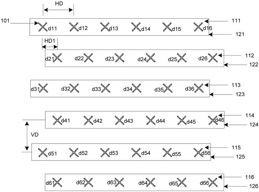
[0038] Adjacent rows of the radiating element array are arranged in a horizontally offset manner, such as image 3 shown. A plurality of radiating units 101 are arranged in a row, the horizontal spacing of the radiating units is HD, the vertical spacing is VD, and the horizontal stagger distance between adjacent rows is HD1. Preferably, the number of radiation units in each row is 6 and the horizontal spacing is equal, and the number of rows is 6 and the vertical spacing of adjacent rows is equal; preferably, the second row of radiation units 112, the fourth row of radiation units 114, and the sixth row The radiating units 116 are offset to the right by HD1 relative to the first row 111 ; the ...

Embodiment 2

[0046] An embodiment of the present invention is a dual-polarized three-beam antenna with a fixed downtilt angle covering an ultra-wide frequency band of 1700-2700 MHz. Compared with Embodiment 1, the arrangement of the radiating elements is consistent, the number of beamforming networks is reduced from 6 to 2, and the phase shifter is simplified to a plurality of 3-way power divider circuits. The 3-way power divider circuit is located between the radiation unit and the beam forming network, and is used to control the beam inclination angle and beam width of the elevation plane.

[0047] Preferably, three radiating units at the same horizontal position in each column of the array are connected to a 3-way power divider circuit. image 3 The +45 degree polarized connection of the radiating unit is as Figure 7 shown. The radiation units in the first column are connected as follows, the radiation units d11, d31 and d51 are connected to the output port of the 3-way power divider...


PUM


Abstract

The invention discloses a broadband three-wave-beam array antenna. The broadband three-wave-beam array antenna comprises a metal reflecting plate, a radiation unit array, a plurality of phase compensating circuits, a plurality of beam forming networks and 3x3 Butler matrix circuits, wherein the radiation unit array comprises M subarrays; each subarray comprises N radiation units which are arranged along a horizontal direction; at least one subarray is deviated in the horizontal direction; the plurality of phase compensating circuits are used for performing phase compensation on the subarrays deviated in the horizontal direction; the plurality of beam forming networks comprise two 3x3 Butler matrix circuits and two power distribution networks; and the 3x3 Butler matrix circuits comprise first input ports for forming first wave beams, second input ports for forming second wave beams, and third input ports for forming third wave beams. A scheme in which the radiation units in different lines are deviated in the horizontal direction according to a certain rule is adopted, and certain phase compensation is added for the deviated radiation units in a feed network to restrain grating lobes.

Description

【Technical field】 [0001] The invention relates to a broadband three-beam array antenna, in particular to a broadband three-beam array antenna for improving network speed and capacity. 【Background technique】 [0002] After the fourth-generation mobile communication technology 4G / LTE is commercialized on a large scale, the data traffic in the mobile communication network has increased sharply, and the bandwidth capacity of the mobile communication system in densely populated areas is facing tremendous pressure. Large plazas, transportation hubs, sports centers, performing arts venues, tourist attractions, college student dormitories and other areas are densely populated with tens of thousands or even more than 100,000 people in peak periods. Data traffic and voice calls require extremely high system capacity. In order to increase the capacity of the communication network, the traditional method of increasing the carrier has limited improvement. Another method, which reduces th...

Claims


Application Information

Patent Timeline
Patent Type & Authority Applications(China)
IPC IPC(8): H01Q21/00H01Q23/00
CPCH01Q21/00H01Q23/00H01Q21/24Y02D30/70
Inventor 吴泽海张劭苏振华吴壁群
Owner GUANGDONG BROADRADIO COMM TECH
Why Eureka
Try Eureka