

Multi-band intersected intermodulation test system
An intermodulation test and multi-band technology, which is applied in transmitter monitoring, receiver monitoring, etc., can solve the problems of inability to test intermodulation products and inability to work together
Active Publication Date: 2016-12-21
HANGZHOU JOINTCOM COMM TECH
View PDF8 Cites 8 Cited by
- Summary
- Abstract
- Description
- Claims
- Application Information
AI Technical Summary
Problems solved by technology
The traditional intermodulator can only test the intermodulation of one frequency band. For the test of multiple frequency bands, it is necessary to use multiple intermodulators of different frequency bands. However, the intermodulators of different frequency bands cannot work together and cannot test two The intermodulation products of different frequency band combinations, especially the intermodulation products falling in the third frequency band
Method used
View moreImage
Smart ImageViewing Examples

Examples
Embodiment
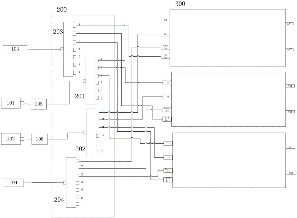
[0045] In this embodiment, the broadband signal source model is Agilent MXG 5181A, the broadband receiver is Agilent MXA9020A, and the power meter is Agilent U2000. The entire test system includes three test modules, a switch box, and two broadband power amplifiers.
Login to View More PUM
 Abstract
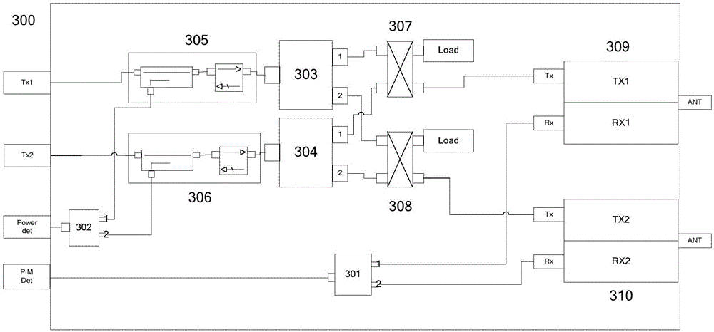
The invention discloses a multi-band intersected intermodulation test system. Two broadband signal sources, two broadband power amplifiers, a broadband receiver and a power meter are used, a switch case switching emission channel and reception channel is added, and thus emission power can be switched to any test module. In the test module, the emission power of each input end is monitored by a coupler, and two test switches are used to switch the output electric bridge of a signal. Through the electric bridge, the signal is mixed and outputted to a diplexer. A first test switch and a second test switch respectively switch two receiving channels and two coupling channels. A third switch common end is connected to the broadband receiver, and other ports switch different module receiving ends. A fourth switch common end is connected to the power meter, other ports switch different module coupling ports, and emitting power is detected. Through independently switching an emission signal 1 channel, an emission signal 2 channel and an intermodulation reception channel, a single frequency band intermodulation test can be realized, and two-frequency-band intermodulation test can be realized too.
Description
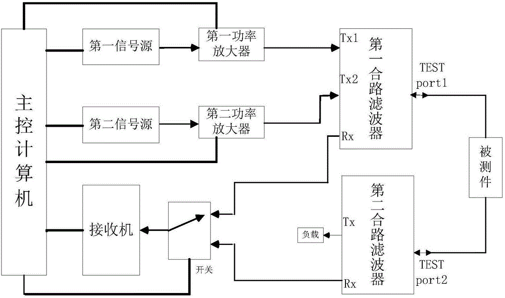
technical field [0001] The invention relates to the technical field of passive device testing, in particular to a multi-band intermodulation test and cross intermodulation test system for passive devices. Background technique [0002] Passive intermodulation analyzer is a test equipment for passive intermodulation of passive devices and systems. The main technical parameters include test power, system residual intermodulation, and operating frequency bandwidth. [0003] Traditional intermodulation analyzers such as figure 1 As shown, the frequency of the first signal source and the second signal source is controlled by the main control computer, and after being amplified by the first power amplifier and the second power amplifier, the first combined filter is output. The tested first combined filter The test terminal is output to the device under test, which can test the reverse and forward intermodulation values of the device under test. Reception mostly uses receivers ...
Claims
Login to View More Application Information
Patent Timeline
 IPC IPC(8): H04B17/29H04B17/15
CPCH04B17/15H04B17/29
Inventor封建华吴浩发张需溥金莉喻国建陈善戴劲
OwnerHANGZHOU JOINTCOM COMM TECH