
Radial-adjustment uniform-field portable nuclear-magnetic-resonance detection permanent magnet

A nuclear magnetic resonance, portable technology, applied in the direction of magnets, magnetic objects, measuring devices, etc., can solve the problems of miniaturization of unfavorable magnet structure, complex permanent magnet structure, increase of magnet volume, etc., to solve the end effect and homogenize the center. Magnetic field distribution, the effect of reducing the difficulty of assembly

Inactive Publication Date: 2016-12-28
SOUTHEAST UNIV
View PDF7 Cites 36 Cited by
  • Summary
  • Abstract
  • Description
  • Claims
  • Application Information

AI Technical Summary

Problems solved by technology

[0004] In summary, the use of additional devices such as hemispherical magnet structures to compensate the axial magnetic field of the magnets will lead to more complex permanent magnet structures and increase the volume of the magnets, which is not conducive to the miniaturization of the magnet structure; the Mandhalas multilayer array structure adjusts the layer spacing to improve the uniformity of the magnetic field However, as the gap increases, the flux leakage increases, and the height of the magnet is still too large, resulting in a larger magnet volume

Method used


Image

  • Radial-adjustment uniform-field portable nuclear-magnetic-resonance detection permanent magnet
  • Radial-adjustment uniform-field portable nuclear-magnetic-resonance detection permanent magnet
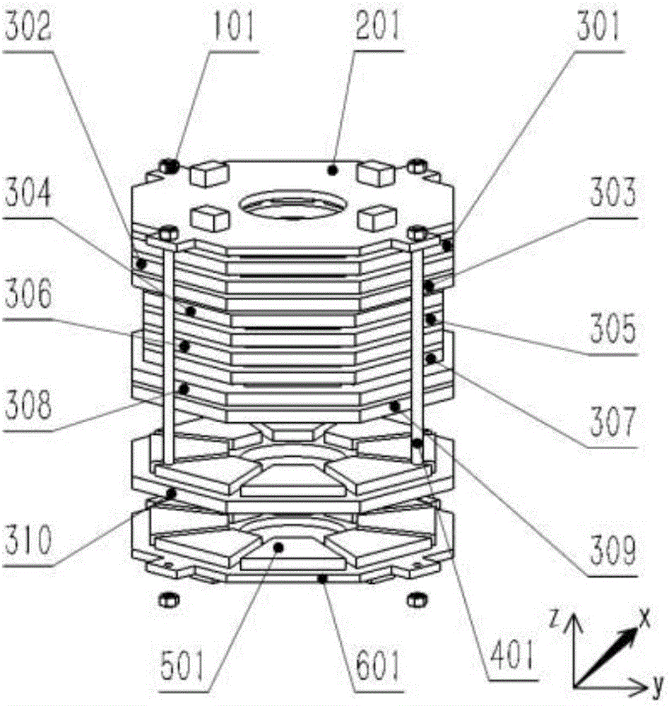
  • Radial-adjustment uniform-field portable nuclear-magnetic-resonance detection permanent magnet

Examples


Embodiment Construction

[0022] The present invention will be described in further detail below in conjunction with the accompanying drawings and embodiments.

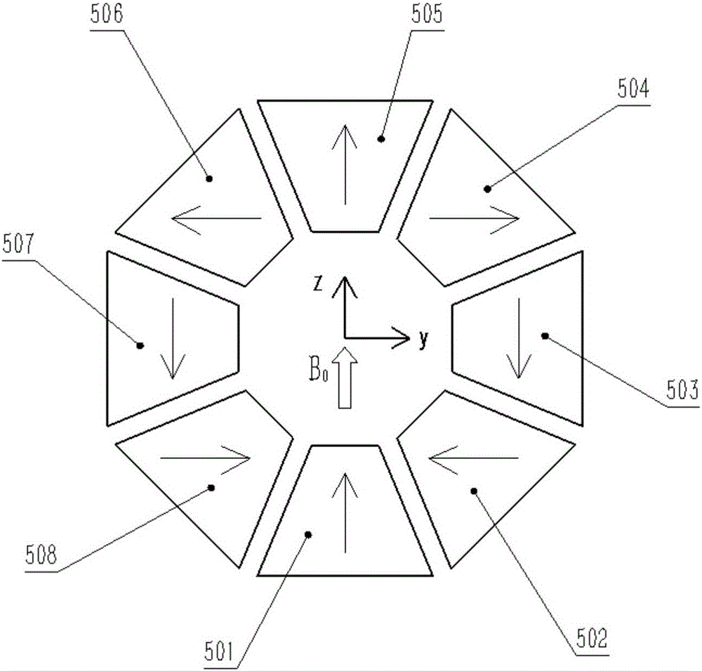
[0023] like figure 1 As shown, the present invention provides a portable NMR detection permanent magnet with radially adjusted uniform field. The magnet structure includes permanent magnetic rings (501,...,508), base plates (201,301...,310,601) and copper screws ( 401) and nuts (101). In this embodiment, the permanent magnet is formed by stacking M=11 layers of sub-magnetic ring arrays, and the ratio of the inner and outer diameters of each layer of sub-magnetic rings is optimized and adjusted. The sub-magnetic ring is composed of N=8 identical trapezoidal magnetic blocks (501,...,508) arranged in a circular array, embedded in the groove of the base plate (201,301...,310,601) and fixed with special glue, and then the base plate ( 201,301,...,310,601) are stacked layer by layer and then fixed with screw rods (401) and nuts (101).

[0024] li...


PUM


Abstract

The invention relates to a portable NMR detection permanent magnet for radially adjusting a uniform field, which mainly includes a radially adjusting permanent magnet and a base plate. The radially adjusted permanent magnet provides the main magnetic field of the magnet, which is composed of M-layer sub-magnetic ring arrays stacked layer by layer. The inner and outer diameters of each layer of sub-magnetic rings are different, and the magnetic field distribution in the center of the magnet is controlled by adjusting the ratio of inner and outer diameters; the base plate includes upper and lower cover plates and the middle M-1-layer substrate, the upper and lower cover plates are placed at both ends of the magnet, grooves are processed on both sides of the middle substrate, and the magnetic blocks are embedded to form a sub-magnetic ring. The distance between each layer is determined by the substrate; Layers are stacked, and finally the entire magnet structure is fixed with screws. The portable NMR detection permanent magnet provided by the present invention adopts a radial adjustment method to improve the uniformity of the magnetic field, effectively solves the impact of the end effect caused by the limited height of the cylindrical magnet, and realizes the generation of a high uniformity magnetic field in a small volume, which is in line with the future The requirement of portability and miniaturization of NMR system.

Description

technical field [0001] The invention relates to a nuclear magnetic resonance permanent magnet structure design, which can generate a uniform static magnetic field for NMR detection in a magnet structure with a small volume. Background technique [0002] Nuclear magnetic resonance (Nuclear Magnetic Resonance, NMR) technology has developed rapidly in recent years, and is widely used in physics, chemistry, life medicine, agricultural food safety, geological exploration, surveying, etc. Wells and other fields. However, the NMR magnets currently used increase the amount of magnetic materials used in order to increase the magnetic field strength and uniformity, resulting in a bulky and bulky body that does not meet the future development needs of portability and miniaturization. The Halbach array structure permanent magnet (magic ring magnet) has received extensive attention since it was proposed. The characteristic of this structure is that the magnetic field strength on one sid...

Claims


Application Information

Patent Timeline
IPC IPC(8): H01F7/02G01R33/383
CPCH01F7/0278G01R33/383H01F7/021
Inventor 倪中华易红胡剑雄陆荣生
Owner SOUTHEAST UNIV
Learn More