Hydraulic transmission device, fluid infusion equipment and manufacturing methods of hydraulic transmission device and fluid infusion equipment

A hydraulic transmission device and hydraulic fluid technology, applied in the direction of infusion sets, syringes, etc., can solve the problems of unfavorable patients, many moving parts, and high price, and achieve the effects of convenient going out, accurate flow selection, and easy wear

Inactive Publication Date: 2017-01-04
MEDTRONIC INC
View PDF10 Cites 3 Cited by
  • Summary
  • Abstract
  • Description
  • Claims
  • Application Information

AI Technical Summary

Problems solved by technology

Among them, the electronic insulin pump integrates basal injection and bolus injection into an infusion system, which is often complex in structure, heavy in weight, and expensive
However, the existing mechanical insulin pumps generally separate the basal injection and the bolus injection into two parallel systems, which are finally aggregated to the same infusion port for injection. Mechanical insulin pumps often directly provide push power through compressed springs. There are many moving parts, the volume is large and the accuracy is relatively poor, and often only a single flow of insulin basal injection can be provided, which is not conducive to real-time adjustment of patients according to their own diet and physical condition

Method used


Image

  • Hydraulic transmission device, fluid infusion equipment and manufacturing methods of hydraulic transmission device and fluid infusion equipment
  • Hydraulic transmission device, fluid infusion equipment and manufacturing methods of hydraulic transmission device and fluid infusion equipment
  • Hydraulic transmission device, fluid infusion equipment and manufacturing methods of hydraulic transmission device and fluid infusion equipment

Examples


no. 1 approach

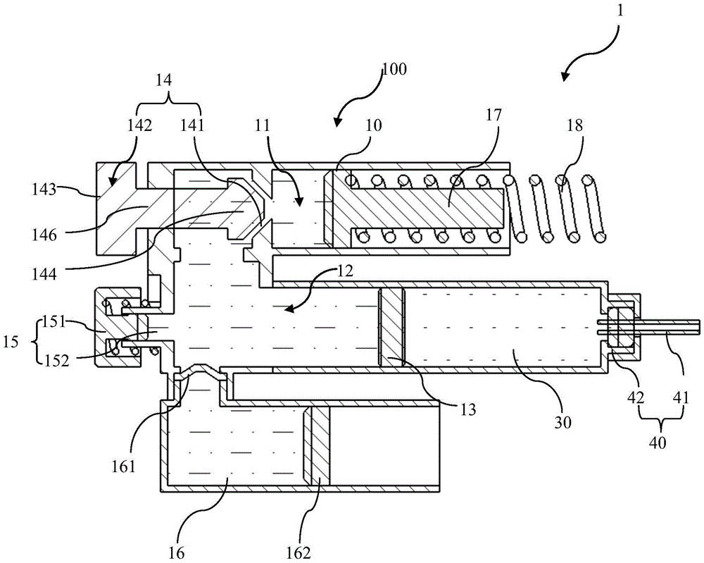
[0033] figure 1 is a cross-sectional view of a fluid infusion device including a hydraulic transmission according to one embodiment of the present invention. Such as figure 1 As shown, the hydraulic transmission device of the present invention can be used as a component of a fluid infusion device for applying a driving force to the second piston through hydraulic fluid to deliver the infusion fluid in the liquid storage chamber of the fluid infusion device to the patient, wherein The infusion fluid may include (but not limited to) insulin, and may also be other pharmaceutical fluids such as analgesics. Such as figure 1 As shown, the fluid infusion device 1 includes: a housing (not shown, for example, the housing may be adapted to be worn on the patient's skin for portable use by the patient, or may be other settings that are not worn on the patient's skin but are convenient for the patient's portable use, For example, a fluid infusion device is worn on a belt, placed in a p...

no. 2 approach

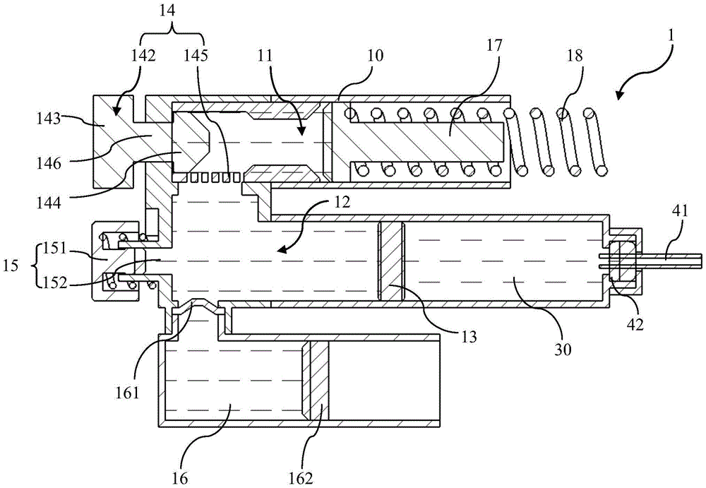
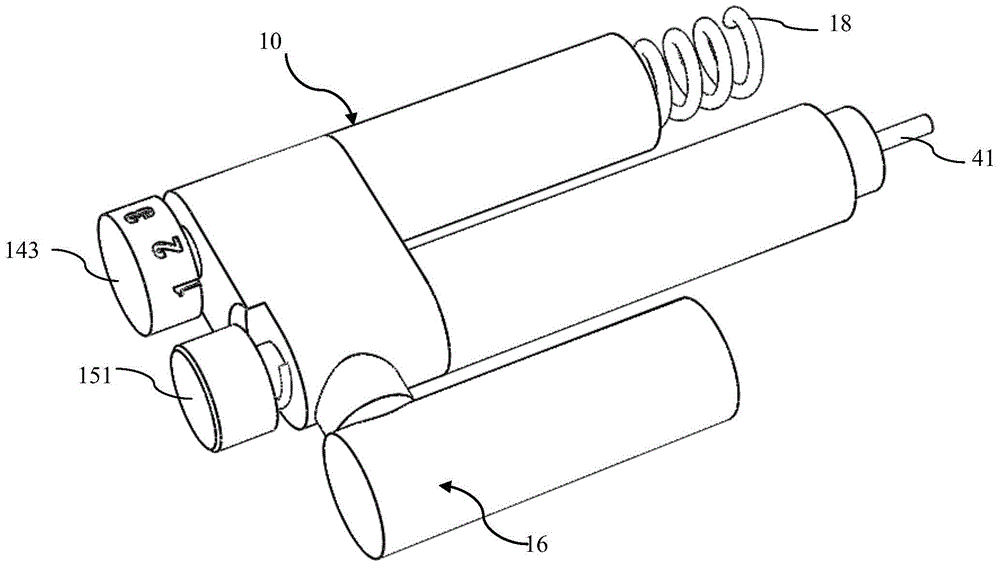
[0042] figure 2 is a cross-sectional view of a fluid infusion device including a hydraulic transmission device according to another embodiment of the present invention; image 3 for figure 2 A schematic diagram of the three-dimensional structure of the fluid infusion device shown. Such as figure 2 and image 3 As shown, the structure of the fluid infusion device including the hydraulic transmission device is substantially the same as the structure of the fluid infusion device including the hydraulic transmission device in the first embodiment, the difference is that in this embodiment, the first flow-restricting channel 145 is used instead of the first The current limiting channel 141 in the embodiment.

[0043] The flow-limiting channel 145 included in the flow selection mechanism 14 in this embodiment can be a plurality of through holes located on the partition wall between the first hydraulic chamber 11 and the second hydraulic chamber 12, and a plurality of through ho...

no. 3 approach

[0046] Figure 4 is a cross-sectional view of a fluid infusion device including a hydraulic transmission device according to yet another embodiment of the present invention; Figure 5A and Figure 5B respectively Figure 4 The schematic diagram of opening and closing of the channel selection mechanism in the hydraulic transmission shown; Figure 6 for Figure 4 A schematic diagram of the appearance of the fluid infusion device shown; Figure 7 yes Figure 4 A schematic diagram of the three-dimensional structure of the fluid infusion device shown. Such as Figure 4 to Figure 7 As shown, the structure of the fluid infusion device including the hydraulic transmission device is substantially the same as that of the fluid infusion device including the hydraulic transmission device in the first embodiment, the difference mainly lies in the flow selection mechanism in the hydraulic transmission device.

[0047] In this embodiment, the flow selection mechanism 24 of the hydraul...


PUM


Abstract

The invention provides a hydraulic transmission device for fluid infusion equipment, the fluid infusion equipment and manufacturing methods of the hydraulic transmission device and the fluid infusion equipment. The fluid infusion equipment is used for applying medicine to a patient and comprises a liquid storage chamber. The hydraulic transmission device comprises a first hydraulic chamber, a second hydraulic chamber and a flow selection mechanism. The first hydraulic chamber is connected with an external power source providing driving force through a first piston, and hydraulic fluid is contained in the first hydraulic chamber. Hydraulic fluid is contained in the second hydraulic chamber. The first hydraulic chamber and the second hydraulic chamber are communicated through the flow selection mechanism, and the hydraulic fluid transfers driving force to a second piston located between the liquid storage chamber and the second hydraulic chamber so as to convey infusion fluid in the liquid storage chamber to a patient; besides, the flow selection mechanism is arranged to be capable of selecting the flow of the hydraulic fluid flowing to the second hydraulic chamber from the first hydraulic chamber so as to selectively determine the flow of the infusion fluid conveyed to the patient from the liquid storage chamber. By means of the device, the equipment and the methods, injection at multiple insulin base amounts with different flows can be provided; the size of an insulin pump can be reduced, and the patient can wear the insulin pump more conveniently.

Description

technical field [0001] The present invention relates to the field of fluid infusion for administering medicine to patients, in particular, to a hydraulic transmission device for a fluid infusion device, a fluid infusion device with the hydraulic transmission device and a manufacturing method thereof. Background technique [0002] Diabetes is a metabolic disease characterized by high blood sugar. Hyperglycemia is generally due to defective insulin secretion or impaired biological action, or a combination of both. Long-term high blood sugar in diabetic patients will lead to chronic damage and dysfunction of multiple body organs (such as eyes, kidneys, heart, blood vessels, nervous system, etc.). [0003] The clinical diagnosis of diabetes can be divided into type 1 diabetes and type 2 diabetes. Type 1 diabetes, also known as insulin-dependent diabetes, usually appears in childhood or adolescence, and is a disease that is inherited in families. Type 1 diabetes is an autoimmu...

Claims


Application Information

Patent Timeline
Patent Type & Authority Applications(China)
IPC IPC(8): A61M5/178
Inventor 冯勇薛跃强黄霖
Owner MEDTRONIC INC
Why Eureka
Try Eureka