The Processing Technology of the Hole on the Crossbeam of the Automobile Dashboard

A technology for automobile dashboard and processing technology, which is applied in the direction of perforation tools, metal processing equipment, manufacturing tools, etc., can solve the problems such as the inability of the core mold Z to move radially, and it is difficult to remove the mold.

Active Publication Date: 2018-06-08
LINGYUN INDAL CORP
View PDF9 Cites 0 Cited by
  • Summary
  • Abstract
  • Description
  • Claims
  • Application Information

AI Technical Summary

Problems solved by technology

[0003] The purpose of the present invention is to provide a processing method for the hole on the crossbeam of the automobile instrument panel to solve the problem that when the crossbeam hole of the automobile instrument panel is processed, since the inner diameter of the crossbeam tube is almost the same as the outer diameter of the mandrel Z, the mandrel Z cannot radially Moving, hard to unmold issues

Method used


Image

  • The Processing Technology of the Hole on the Crossbeam of the Automobile Dashboard
  • The Processing Technology of the Hole on the Crossbeam of the Automobile Dashboard
  • The Processing Technology of the Hole on the Crossbeam of the Automobile Dashboard

Examples


specific Embodiment approach 1

[0012] Specific implementation mode 1: Please refer to Figure 3 to Figure 8 , this embodiment is completed by the following steps:

[0013] 1. Docking the left mandrel 1 with the right mandrel 2 to form a mandrel Z, the mandrel Z is a rod-shaped overall structure;

[0014] The right end face of described left mandrel 1 is provided with a regular quadrangular pyramid 1-1, and the centerline of regular quadrangular pyramid 1-1 coincides with the axis line of left mandrel 1, and the center line of described right mandrel 2 A regular square pyramid hole 2-1 is arranged on the left end face, the center line of the regular square pyramid hole 2-1 coincides with the axis line of the right mandrel 2, and the regular square pyramid 1-1 is inserted into the regular square pyramid hole 2-1 A detachable fixed fit is formed in the middle, and a die hole 3 is opened on the circumferential surface of the annular seam 3-1 where the left mandrel 1 and the right mandrel 2 are butted, and the ...

specific Embodiment approach 2

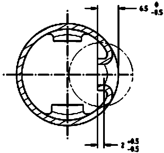
[0026] Specific implementation method two: please refer to Figure 9 The difference between this embodiment and Embodiment 1 is that the center line of the die hole 3 is located on the regular quadrilateral diagonal of the regular quadrangular pyramid 1-1 and the regular quadrangular pyramid hole 2-1 cross-section, and the regular quadrangular pyramid 1-1 and An interference fit is formed between one set of opposite faces of the regular quadrangular pyramid hole 2-1, and a gap fit is formed between the other set of opposite faces, and the fit gap is 0.04 mm to 0.06 mm. In this way, the interference fit formed between the regular quadrangular pyramid 1-1 and a group of opposite faces of the regular quadrangular pyramid hole 2-1 is to form a reliable fixed connection between the left mandrel 1 and the right mandrel 2, The clearance fit formed between another set of opposite faces is required for positioning. And if the two sets of opposite faces form an interference fit, it is ...

specific Embodiment approach 3

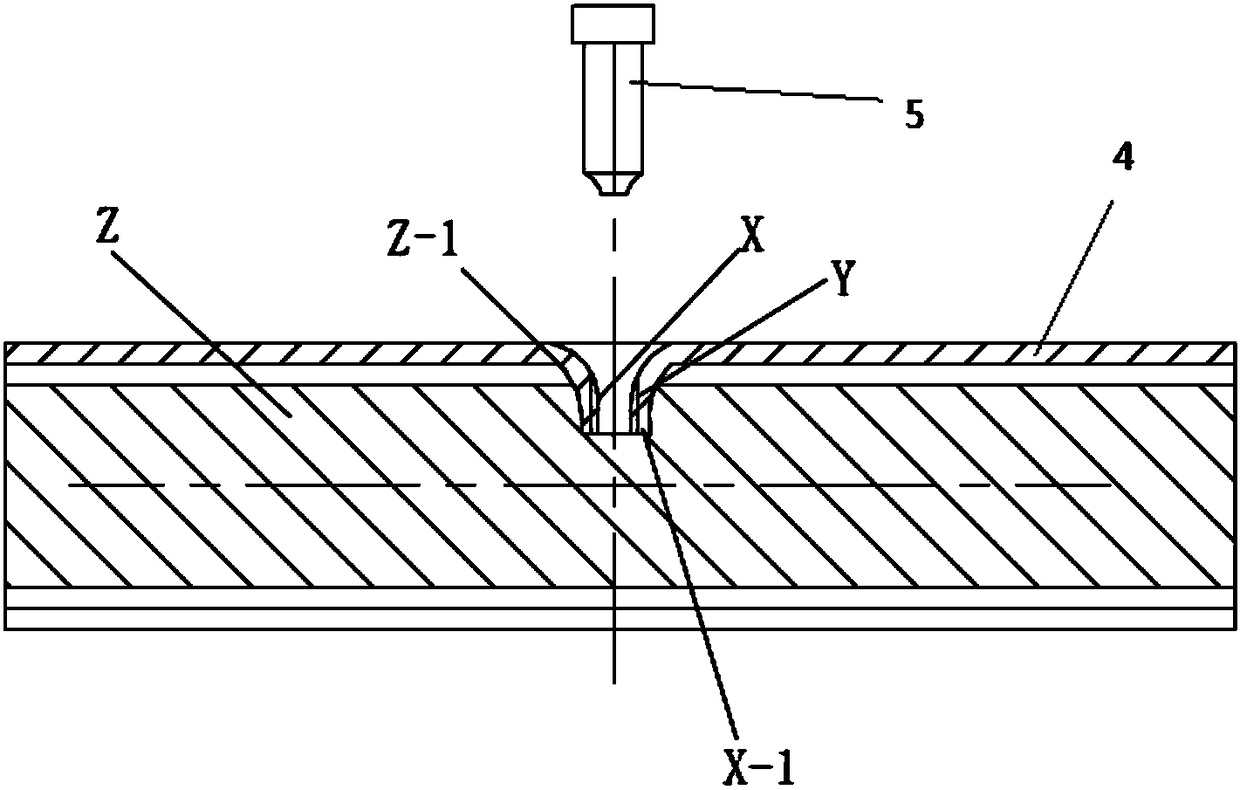
[0028]Specific implementation mode three: please refer to Figure 10 , the difference between this embodiment and Embodiment 1 is that the core mold Z is composed of the middle section including the left core mold 1 and the right core mold 2, the left extension section Z-3 and the right extension section Z-4, and the left extension section Z -3 and the outer surface diameter of the right extension section Z-4 are smaller than the outer surface diameter of the middle section, and the gap between the outer surface diameter of the middle section and the inner hole of the beam tube 4 is 0.15 to 0.25 mm. The advantage of this setting is that the gap between the outer surface diameter of the middle section and the inner hole of the beam tube 4 is relatively small, and when the inner convex part X-1 is filled into the mold hole Z-1 of the core mold Z, the left core mold 1 and the splitting force of the mandrel 2 on the right are basically offset by the frictional force that hinders m...


PUM

PropertyMeasurementUnit
diameteraaaaaaaaaa
diameteraaaaaaaaaa
lengthaaaaaaaaaa

Abstract

The invention relates to a machining technology method of a hole in an automobile instrument board cross beam. The problems that when a hole in an automobile instrument board cross beam is machined, due to the fact that the inner diameter of a cross beam pipe and the outer diameter of a core mold Z have little difference, the core mold Z cannot radially move, and mold stripping is difficult are solved. The method comprises the following steps that a left side core mold and a right side core mold are in abut joint to form the core mold, and the core mold is of a rod-shaped whole structure; the core mold enters an inner hole of a cross beam pipe, a mold punching hole is formed in the position, to be punched, of the cross beam pipe; the cross beam pipe is fixed to a punching machine, and the position to be punched is upward; the position of a punching mechanism is adjusted on a guide rail, a punching mold of the punching mechanism aligns at the position to be punched of the cross beam pipe below the mold, the one-time downward stroke is completed, an inner protrusion portion is punched on the cross beam pipe, and an inner cavity of the mold punching hole is filled with the inner protrusion portion; the punching mold returns upwards; the left side core mold and the right side core mold are pulled away from the two sides of the inner protrusion portion, which are punched in the cross beam pipe.

Description

technical field [0001] The invention relates to a processing method for a hole on an automobile instrument panel beam. Background technique [0002] The car dashboard beam is the frame that supports the human-machine interface and installs the instrumentation equipment. The automobile instrument panel beam and other safety parts constitute a safety system, which is a structural part to protect the driver and passengers in the car, and its strength and rigidity are the primary indicators of its performance. like figure 1 and figure 2 As shown, the cross-section of the automobile instrument panel beam is generally in the shape of a circular tube, and the structure of holes needs to be processed on the automobile instrument panel beam to install and connect other parts. In order to install parts through threads easily and with high strength, it is necessary to punch holes in the tube as the raw material to form such as image 3 The elevation X of the cylindrical hole shown...

Claims


Application Information

Patent Timeline
Patent Type & Authority Patents(China)
IPC IPC(8): B21D53/88B21D28/28B21D28/34
CPCB21D28/246B21D28/28B21D28/34B21D53/88
Inventor 段晓刚张黎黎耿秋勇刘宏生常乐王英丽高阳张荣晨朱会锋左荣召唐奇金郭旭于奇李鹤鹏林东浩王震王志强石伟赵骞张滨王乾
Owner LINGYUN INDAL CORP
Why Eureka
Try Eureka