Peeling, shearing, riveting and twisting integrated machine

An all-in-one machine and auxiliary mechanism technology, applied in the direction of cable installation devices, electrical components, equipment for dismantling/armouring cables, etc., can solve the problems of inability to reduce labor costs, high labor intensity, and occupying a lot of space, so as to improve labor productivity , Reduce labor costs, improve the effect of space utilization

Active Publication Date: 2017-01-04
支友光
View PDF5 Cites 6 Cited by
  • Summary
  • Abstract
  • Description
  • Claims
  • Application Information

AI Technical Summary

Problems solved by technology

The early processing stage is done manually by different operators at different stations, the production efficiency is extremely low, the labor intensity is high, and the product standards produced are not uniform
[0003] In order to solve the problems of high labor cost and low production efficiency, some manufacturers have designed cable cutting machines, cable stripping machines, terminal crimping machines and nut tightening machines
After adopting the cable cutting machine, cable stripping m

Method used


Image

  • Peeling, shearing, riveting and twisting integrated machine
  • Peeling, shearing, riveting and twisting integrated machine
  • Peeling, shearing, riveting and twisting integrated machine

Examples


Embodiment approach 1

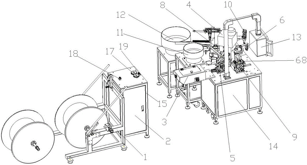
[0042] An all-in-one stripping, shearing, riveting and screwing machine, comprising a pay-off frame 1, an auxiliary mechanism 2, a wire feeding mechanism 3, a terminal mechanism 4, a terminal vibrating plate 11, a rotating mechanism 5, an introducing mechanism 6, a feeding mechanism 7, and a connector vibrating plate 12. Cap screwing mechanism 8, cutting and peeling mechanism 9, guiding mechanism 68, wire taking mechanism 10, PLC controller, touch screen 13 and frame 14.

[0043] Pay-off rack 1: lift the cable reel off the ground so that the cable reel can rotate on it. In order to conveniently place the cables on the pay-off rack, there is also an auxiliary lever on the pay-off rack. Before unwinding, the auxiliary lever can be tilted to the ground, and the cable will be pushed up the pay-off along the slope of the auxiliary lever. After the cable is placed, lift the auxiliary lever up and place it on the pay-off rack.

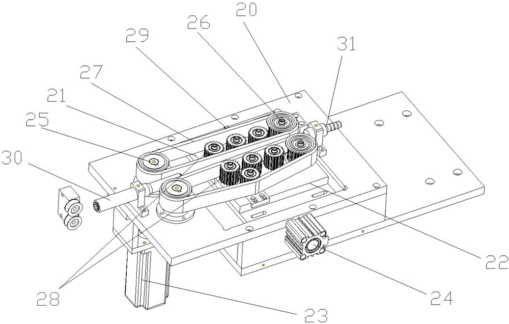
[0044] Auxiliary mechanism 2: Pull the cable to make i...

Embodiment approach 2

[0059] The scheme is basically the same as that of Embodiment 1, and will not be described here. The purpose of designing Embodiment 2 is to improve the processing efficiency of cables and connectors. The difference from Embodiment 1 lies in: the introduction mechanism, the feeding mechanism, and the cap screwing mechanism , Connector vibrating plate 12, wire-taking mechanism 10 all adopt two groups, two groups of lead-in mechanism, sending and taking mechanism, cap screwing mechanism, wire-taking mechanism 10, symmetrically arranged on both sides of cutting and stripping mechanism. Two groups of connector vibrating plates 12 are arranged at appropriate positions beside the frame. Realize the processing of cables and connectors by two sets, which greatly improves the production efficiency.


PUM


Abstract

The invention discloses a peeling, shearing, riveting and twisting integrated machine. The peeling, shearing, riveting and twisting integrated machine comprises a wire feeding mechanism, a rotating mechanism, a terminal mechanism, a guiding-in mechanism, a feeding and taking mechanism, a cap twisting mechanism, a cutting and peeling mechanism, a wire taking mechanism, a terminal vibrating plate, a connector vibrating plate, a main air valve, a PLC and a touch screen as well as a pay-off rack, an auxiliary mechanism and a connector vibrating plate which are arranged outside the frame. The auxiliary mechanism, the wire feeding mechanism, the terminal mechanism, the terminal vibrating plate, the rotating mechanism, the guiding-in mechanism, the feeding and taking mechanism, the cap twisting mechanism, the connector vibrating plate, the cutting and peeling mechanism, the wire taking mechanism, the main air valve and the touch screen are respectively connected with the PLC electrically. After the scheme is adopted, the original scattered stations are integrated on equipment for processing and treating, production cost is reduced, and space utilization rate of the workshop is increased. The equipment is relatively high in degree of intelligence and convenient to operate.

Description

technical field [0001] The invention relates to the field of automation equipment, in particular to an all-in-one machine capable of peeling and cutting cables, riveting terminals, and then automatically tightening and fixing them with connectors. Background technique [0002] The processing technology of the existing cables and connectors is as follows: Step 1: Cut the cables to a specified length; Step 2: Strip both ends of the cut cables; Step 3: Strip one end of the stripped cables Terminal crimping; Step 4: Insert the cable with the riveted terminal into the connector and tighten the nut of the connector. The early processing stage is done manually by different operators at different stations, the production efficiency is extremely low, the labor intensity is high, and the product standards produced are not uniform. [0003] In order to solve the problems of high labor cost and low production efficiency, some manufacturers have designed cable cutting machines, cable st...

Claims


Application Information

Patent Timeline
IPC IPC(8): B21F11/00H02G1/12H02G1/14H02G1/00
CPCB21F11/00H02G1/00H02G1/12H02G1/14
Inventor 支友光
Owner 支友光
Why Eureka
Try Eureka