
Spirally wound gasket outer ring groove milling equipment and use method thereof

A spiral wound gasket and outer ring technology, applied in milling machine equipment, milling machine equipment details, metal processing equipment and other directions, can solve problems such as unfavorable effective workshop management, groove deviation, and low work efficiency.

Active Publication Date: 2017-01-04
慈溪埃弗龙密封件有限公司
View PDF7 Cites 2 Cited by
  • Summary
  • Abstract
  • Description
  • Claims
  • Application Information

AI Technical Summary

Problems solved by technology

Most of the traditional metal spiral wound gasket outer ring milling machines only have a feeding device and a cutting device, but lack an automatic unloading device, and the workpieces need to be manually taken out and stacked in an orderly manner, which not only has low work efficiency, but also has high strength.
Since there is no gasket storage device, after the workpiece is processed, the gasket is often put directly into the receiving frame or placed on the round tube in a rough manner, and because the outer ring of the gasket to be processed has different sizes and specifications, each time the gasket After milling slots, manual sorting and stacking are required, otherwise the environment in the workshop will be chaotic, which is not conducive to the effective management of the workshop, which also increases the workload of operators and reduces work efficiency
[0003] On the other hand, since the traditional shim milling machine does not have auxiliary support devices, when processing large-size shims, it often causes deformation problems during the processing of large-size shims, resulting in deviation of the required grooves. Cause waste and reduce the pass rate of the outer ring of the metal spiral wound gasket

Method used


Image

  • Spirally wound gasket outer ring groove milling equipment and use method thereof
  • Spirally wound gasket outer ring groove milling equipment and use method thereof
  • Spirally wound gasket outer ring groove milling equipment and use method thereof

Examples


Embodiment Construction

[0035] The following description serves to disclose the present invention to enable those skilled in the art to carry out the present invention. The preferred embodiments described below are only examples, and those skilled in the art can devise other obvious variations.

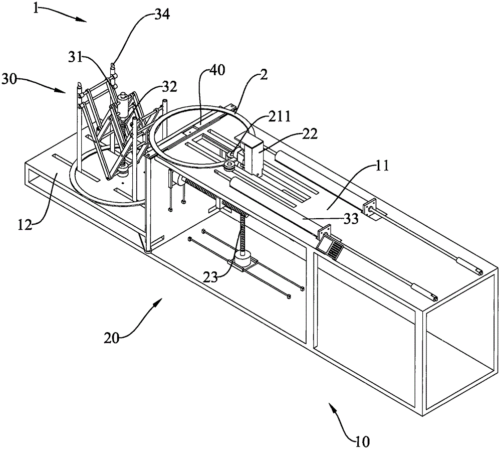
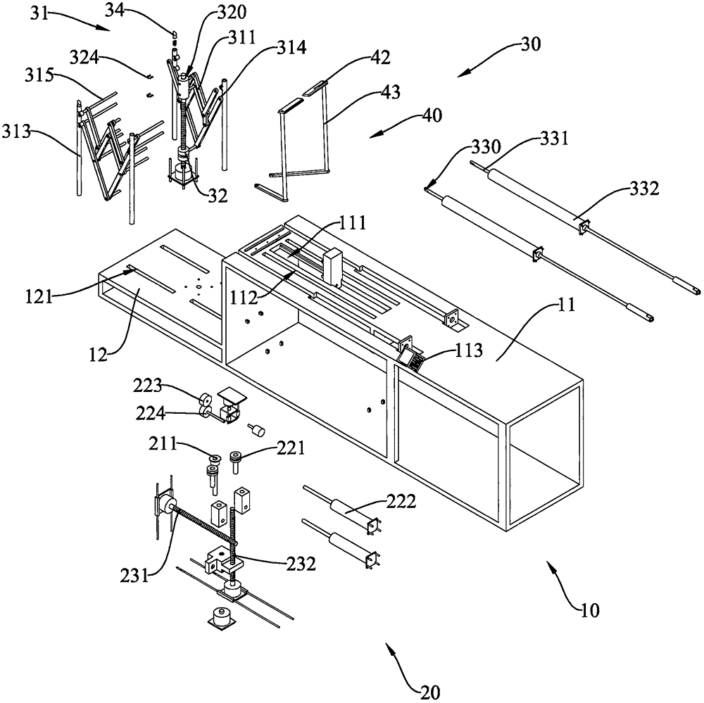
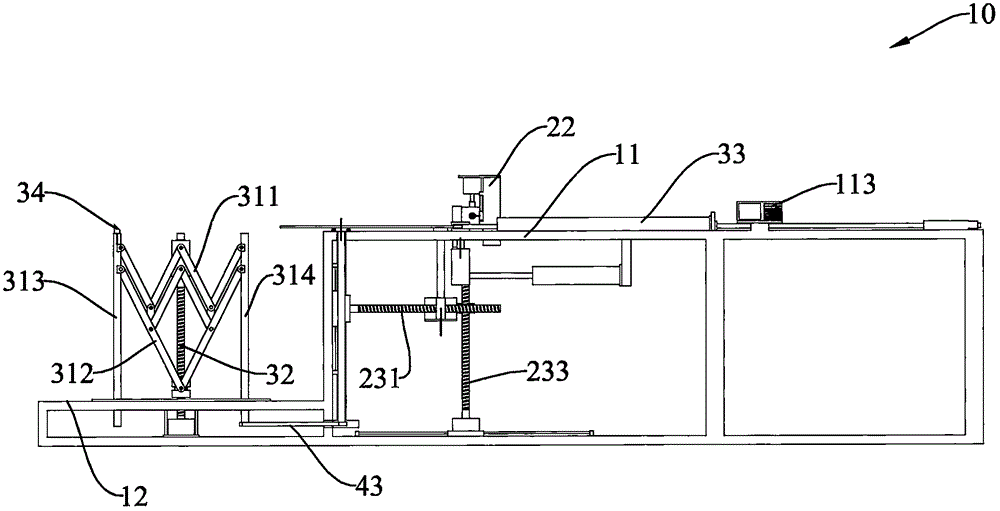
[0036] Such as Figure 1 to Figure 4Shown is a wound gasket outer ring groove milling equipment 1, the spiral wound gasket outer ring groove milling equipment 1 includes a workbench 10, a milling device 20 and a discharge device 30, the workbench 10 includes a milling table 11 and an unloading platform 12, the milling platform 11 is provided with a milling cutter slot 111, the milling device 20 is installed on the milling platform 11, and the milling device 20 includes a milling cutter 211, a transmission wheel unit and a positioning unit 23. The milling cutter 211 is movably connected to the positioning unit 23, and the positioning unit 23 can drive the milling cutter 211 to move horizontally or vertically...


PUM


Abstract

The invention provides spirally wound gasket outer ring groove milling equipment which comprises a working table, a milling device and a discharging device, wherein the working table comprises a groove milling table and a discharging table; a milling groove is formed in the groove milling table; the milling device is mounted in the milling groove, and comprises a milling cutter, a driving wheel unit and a positioning unit; the milling cutter is movably connected with the positioning unit; the driving wheel unit is used for driving the outer ring of a gasket to rotate in a definite position; the discharging device is mounted on the discharging table, and comprises a telescopic unit, a transmission unit and a clamp unit; the telescopic unit is telescopically connected with the transmission unit; the transmission unit can drive the telescopic unit to perform expanding or retracting movement, so that the outer rings of the gaskets of different sizes are guided to be superimposed; and the clamping unit separably clamps the outer rings of the gaskets, so as to clamp and move the outer rings of the gaskets to the discharging table from the groove milling table, and ensure that the outer rings of the gaskets face the telescopic unit. Therefore, the gaskets can fall off automatically for discharging along the outer periphery of the telescopic unit and are superimposed orderly.

Description

technical field [0001] The invention relates to mechanical equipment, in particular to an outer ring groove milling equipment suitable for metal wound gaskets and its application method. Background technique [0002] Groove milling is to cut the required groove with a specific tool, and the milling machine for metal wound gaskets is to cut a circle of grooves on the inner ring of the outer ring of the gasket through the tool. Most of the traditional metal wound gasket outer ring milling machines only have a feeding device and a cutting device, but lack an automatic unloading device, and the workpieces need to be manually taken out and stacked in an orderly manner, which not only has low work efficiency, but also has high strength. Since there is no gasket storage device, after the workpiece is processed, the gasket is often put directly into the receiving frame or placed on the round tube in a rough manner. However, due to the different sizes and specifications of the outer ...

Claims


Application Information

Patent Timeline
IPC IPC(8): B23C3/28B23Q7/00
CPCB23C3/28B23Q7/00
Inventor 叶奇为
Owner 慈溪埃弗龙密封件有限公司
Learn More